Spiral Gear

Inactive Publication Date: 2009-08-27
GRIGORYAN EMIL +2
View PDF4 Cites 0 Cited by
  • Summary
  • Abstract
  • Description
  • Claims
  • Application Information

AI Technical Summary

Benefits of technology

[0006]Performing the diametrical movement of the nut at its butt-ends, through the imitator, increases the size of the gear and reduces its reliability. The rotation of the imitator in both directions through the carrier based on the screw with the help of the spiral catch reduces reliability and operates with noise. In order to eliminate the above disadvantages, this invention provides for control of the compound nut without any additional controlling element and respective mechanism, as well as increasing the reliability of the gear and reducing its size. To achieve these goals, the nut is made of four and more inserts placed in the grooves, in a longitudinal direction of the hole and lean, by their respective inclined surfaces, against the inclined surfaces made at different heights in the same direction on the end parts of the bottoms of the grooves. The spiral support with a conical surface placed coaxially in the hole of the body leans against the conical surfaces made on the butt-ends of the inserts from one side and from the other side the imitator with the respective conical surface, which is positioned coaxial in the hole of the body and has an ability to move only in the direction of the axis, leans against the conical surfaces made on the butt-ends of the inserts, and the spiral disk freely placed in the hole of the body leans through two small balls against two inclined spiral surfaces on the other side of the imitator which have the same height. At the same time in this position, the spiral disk leans against the body with an ability to move in the direction of the axis, and through the key is tied to the screw, and the screw, in turn, is freely placed in the coaxial guides in the ends of the body hole. The inserts have projections at their ends through which they lean against the flat surface of the butt-ends of the grooves when performing the gear.

Problems solved by technology

Performing the diametrical movement of the nut at its butt-ends, through the imitator, increases the size of the gear and reduces its reliability.
The rotation of the imitator in both directions through the carrier based on the screw with the help of the spiral catch reduces reliability and operates with noise.

Method used


Image

  • Spiral Gear
  • Spiral Gear

Examples


Embodiment Construction

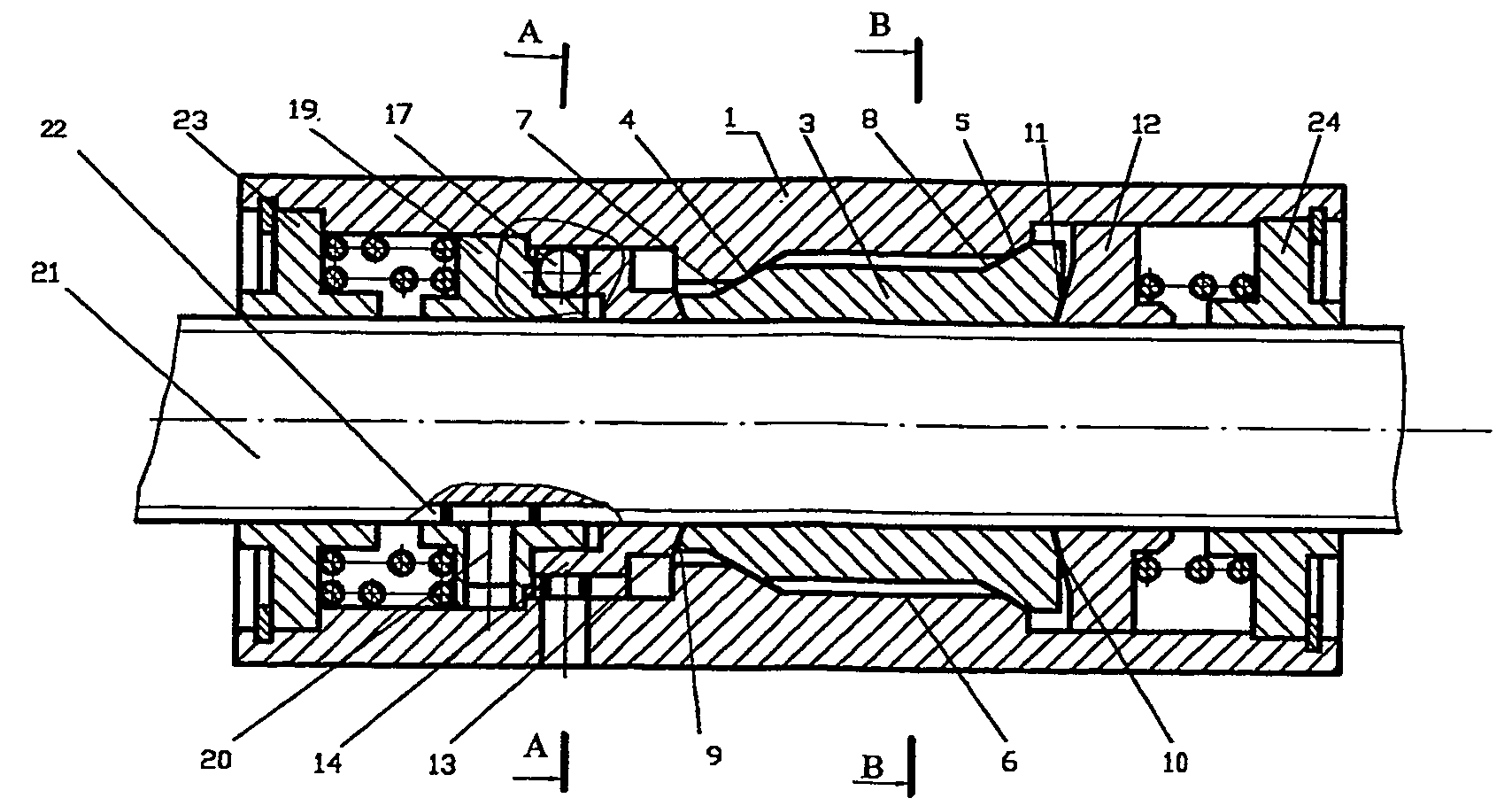
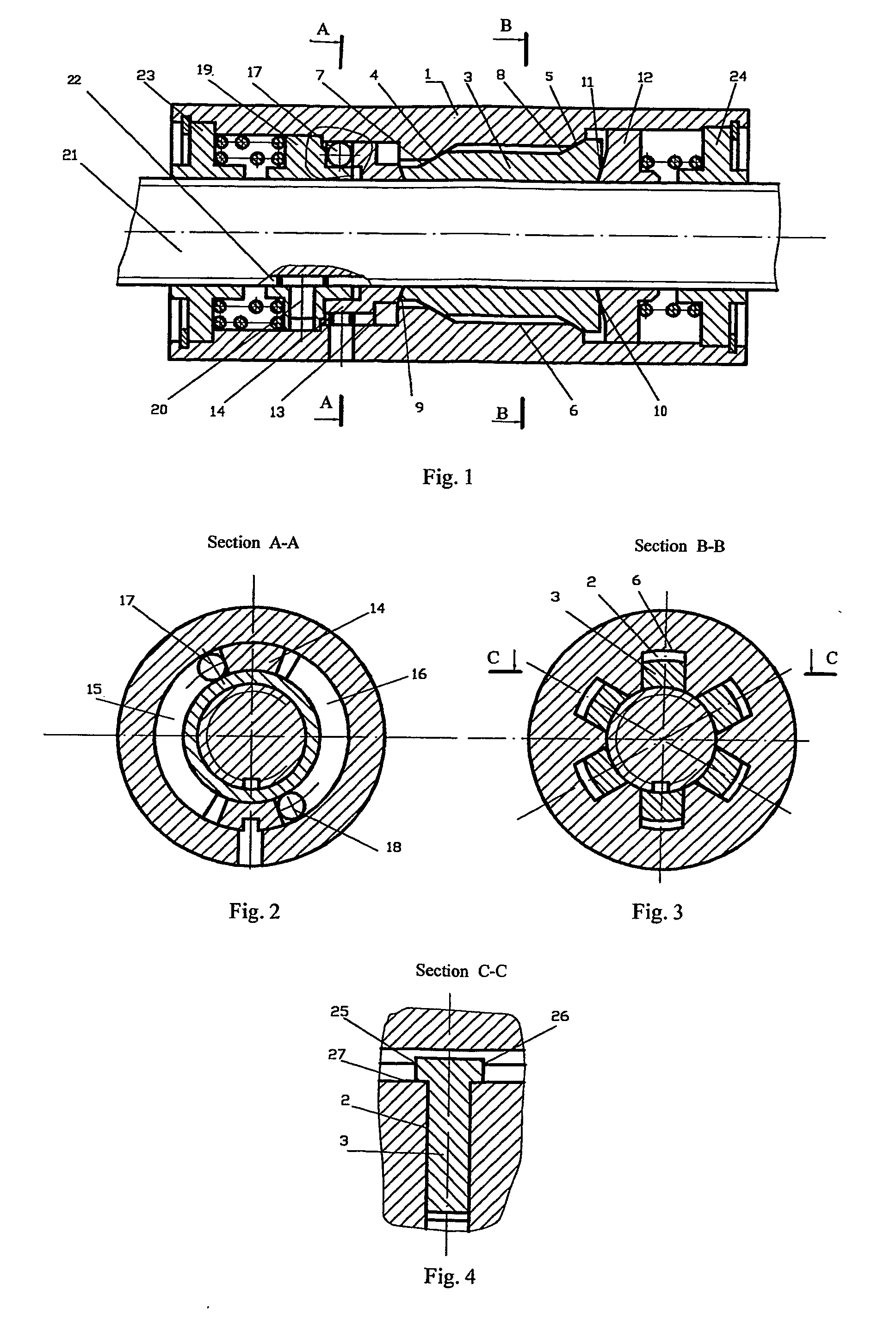
[0012]The spiral gear has a body (1) in which, in the longitudinal direction of the surface of the stepped hole, grooves (2) are made in which inserts (3) are placed which lean against the bottoms (4) of the grooves (2), such as with their respective inclined surfaces (7, 8) against the inclined surfaces (5,6) made on the end parts in the same direction at different height. The spiral support (12) placed coaxial in the hole of the body (1) leans against the conical surfaces (9, 10) made on the butt-ends of the inserts (3) from one side: From the other side the imitator (14) with a respective conical surface (13) is placed coaxially in the hole of the body (1) and has the ability to move only in the direction of the axis. The spiral disk (19) is freely placed in the hole of the body (1) and leans through two small balls (17, 18) against two inclined spiral surfaces made at the same height on the other side of the imitator (14). At the same time in this position, the spiral disk (19) ...


PUM


Abstract

A spiral gear having a body, a compound nut and a screw on which a keyway is made on the longitudinal direction. The nut has four or more inserts placed in the grooves made in the longitudinal direction and leaning against the inclined surfaces made at different heights in the same direction on the end parts of the bottoms of the grooves. The spiral support with the conical surface placed coaxial in the hole of the body leans against the conical surfaces made on the butt-ends of the inserts from one side and leans from the other side the imitator with the respective conical surface. On the other butt-end of the imitator are two small balls against two inclined spiral surfaces made in the direction of the screw which have the same height, and the spiral disk.

Description

BACKGROUND OF THE INVENTION[0001]1. Field of the Invention[0002]This invention relates to machine construction and can be applied in automated equipment, quick clamps, jacks and vices.[0003]2. Discussion of Related Art[0004]Spiral gear are known which have a nut made of two semicircles which, on their butt-ends, have imitators for moving in diametrical directions, a screw with a longitudinal groove on which the carrier is based with a spiral catch, and a handle which fixes the carrier on the body by a spiral pin when the gear is moved by spiral force or load action, such as when lifting weight by a jack (U.S. Pat. No. 5,970,812, MAD F16H 1 / 18, 1999).[0005]The above spiral gear has disadvantages, including that the existence of an additional mechanism of fixing the imitator carrier increases the size of the gear. Also, the possibility of fixing the handle only on the cantilever edge of the screw makes the operation of the gear difficult, whereas with the help of the handle, the semic...

Claims


Application Information

Patent Timeline
IPC IPC(8): F16H1/18F16H25/20
CPCY10T74/19735F16H25/2454
Inventor POGOSYAN, ALBERTPOGOSYAN, SUREN
Owner GRIGORYAN EMIL
Why Eureka
Try Eureka