
Scanning Apparatus and System for Tracking Computer Hardware

a technology for computer hardware and scanning equipment, applied in the field of scanning equipment and system for tracking computer hardware, can solve the problems of insufficient technology, limited method, and inability to dedicate available technologies,

Inactive Publication Date: 2009-08-20
MILEY JAMIE ALAN +1
View PDF55 Cites 17 Cited by
  • Summary
  • Abstract
  • Description
  • Claims
  • Application Information

AI Technical Summary

Benefits of technology

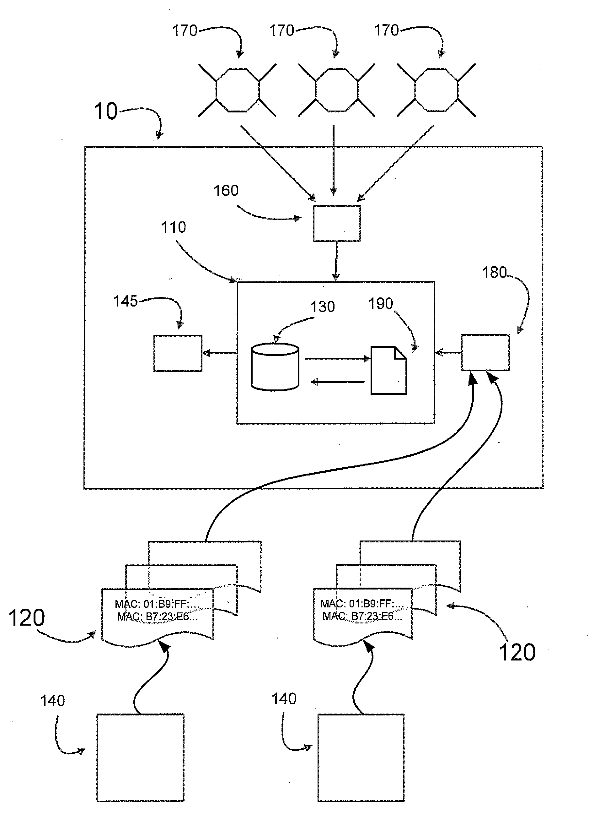
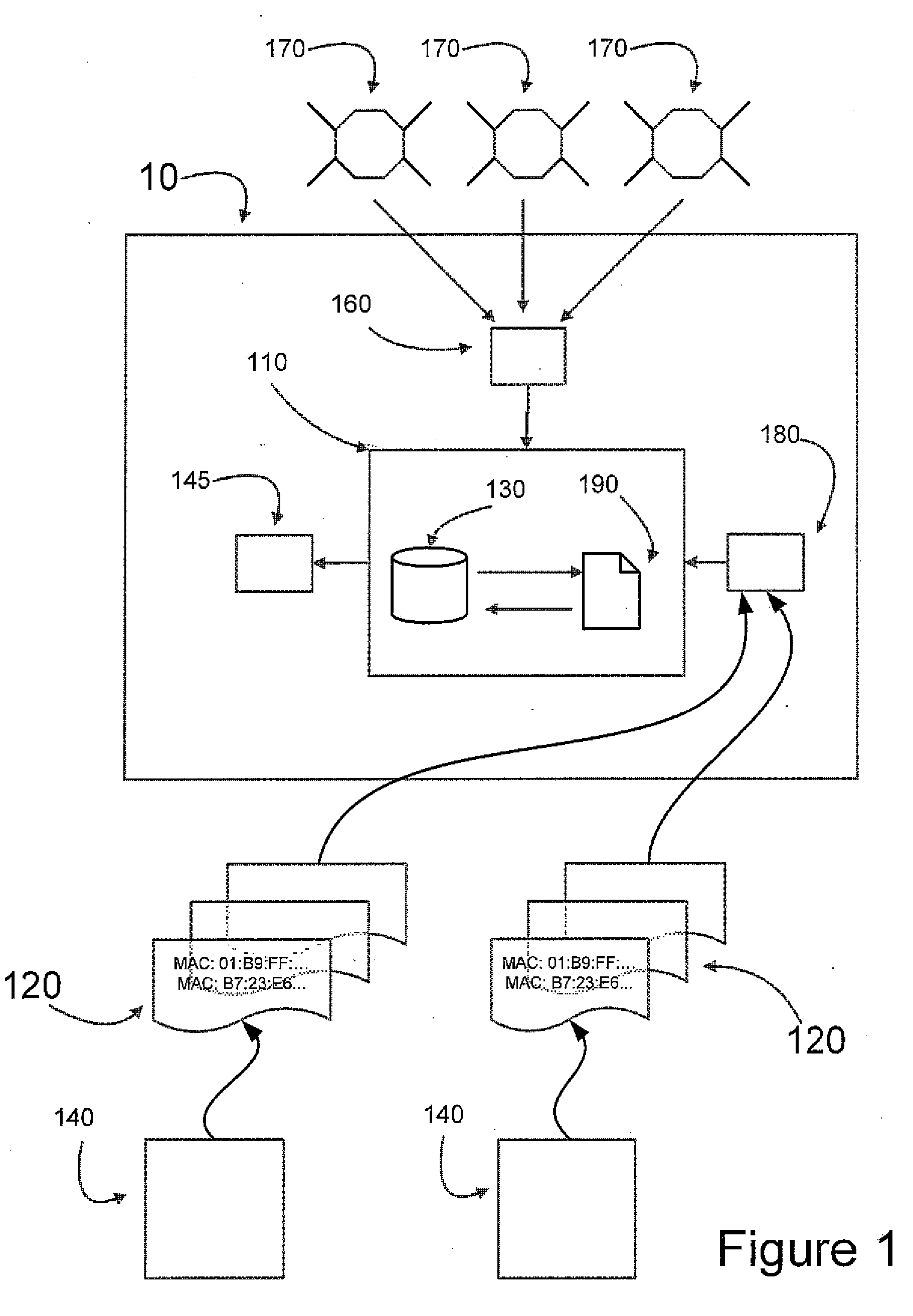
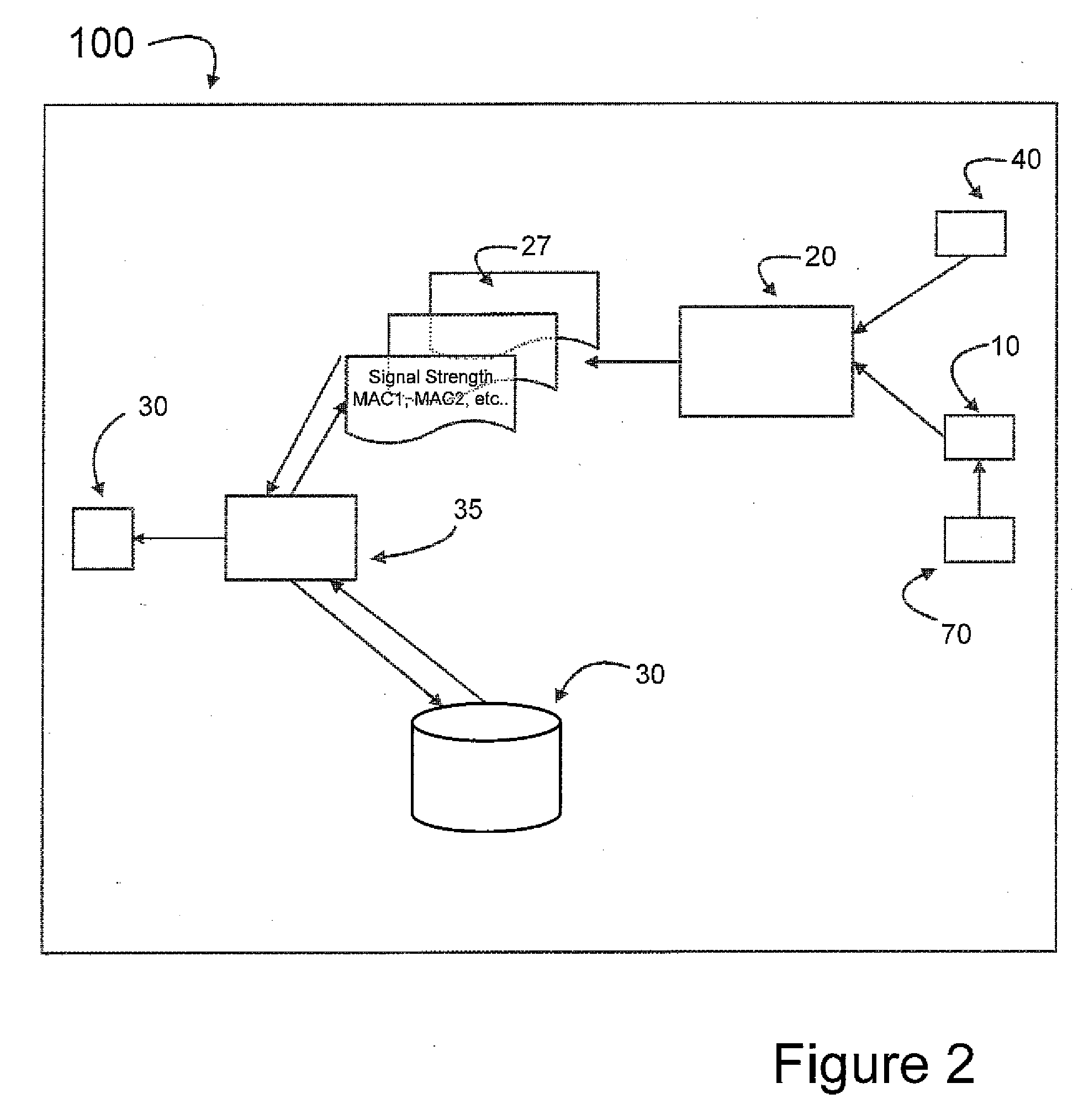
[0041]Still further embodiments of the scanning apparatus identified herein may be configured with additional hardware and software components to generate notifications of a match in a first database with one or more MAC addresses in a second or additional database (MAC match or a hit), and to transmit and / or store a notification message. Still other embodiments may be configured to transform or update one or more databases based on user input, queries, and MAC address matches between one or more databases. Still further embodiments may be configured with software components to measure the signal strength of a device from which a scanned frame is emitted relative to a predetermined point, and / or combined with optional Global Positioning (GPS) software and hardware to determine the location of a device, based on the latitude and longitude of where a particular data frame was captured during the time the scanning apparatus was in range.

Problems solved by technology

Laptops and other mobile computing devices are prone to theft.
Most devices are stored or used, at some point, in an unsecured physical location where they are exposed to risk of theft or where they may accidently be lost.
This method, known in the art, is currently limited to ascertaining the Internet protocol address of the Internet access device (e.g., a router).
Currently, available technologies are not dedicated to locating a particular computer, but rather to locating the wireless access device the computer is using to connect to the Internet.
The user of a stolen device may however, be accessing an unsecured Internet access device or may be gaining unauthorized access.
Thus, it may be difficult to obtain a search warrant using information solely obtained from devices of interest configured with proprietary software presently known in the art.
Also, if a warrant is issued, it may actually be for the wrong dwelling.
This problem is exacerbated in areas where there are a number of residences or locations having wireless access devices in close proximity, such as apartment buildings and dormitories.

Method used


Image

  • Scanning Apparatus and System for Tracking Computer Hardware
  • Scanning Apparatus and System for Tracking Computer Hardware
  • Scanning Apparatus and System for Tracking Computer Hardware

Examples


Embodiment Construction

[0042]For the purpose of promoting an understanding of the present invention, references are made in the text to exemplary embodiments of a scanning apparatus and system for tracking computer hardware, only some of which are described herein. It should be understood that no limitations on the scope of the invention are intended by describing these exemplary embodiments. One of ordinary skill in the art will readily appreciate that alternate but functionally equivalent hardware and software components may be used. The inclusion of additional elements may be deemed readily apparent and obvious to one of ordinary skill in the art. Specific elements disclosed herein are not to be interpreted as limiting, but rather as a basis for the claims and as a representative basis for teaching one of ordinary skill in the art to employ the present invention.

[0043]It should be understood that the drawings are not necessarily to scale, instead emphasis has been placed upon illustrating the principle...


PUM


Abstract

Apparatus and system for tracking computer hardware consisting of a network interface card configured in promiscuous mode capable of passively listening for OSI layer 2 network traffic on a medium for use in the recovery or location of lost or stolen devices. The device of interest, one located, can then be tracked via signal strength. GPS may also be used to track locations where devices of interest have been located.

Description

CROSS-REFERENCE TO RELATED APPLICATIONS[0001]This application claims priority to U.S. Provisional Application No. 61 / 029,988 filed on Feb. 20, 2008.FIELD OF INVENTION[0002]The present invention relates to the field of hardware theft prevention, tracking and recovery.BRIEF DESCRIPTION OF THE DRAWINGS[0003]FIG. 1 illustrates the components of exemplary scanning apparatus for tracking computer hardware.[0004]FIG. 2 illustrates an exemplary scanning process using a scanning apparatus for tracking computer hardware.[0005]FIG. 3 is a block diagram illustrating the scanning process system for tracking computer hardware.[0006]FIG. 4 illustrates an exemplary scanning process using a GPS device to record latitude and longitude information, along with a notification message which is displayed for a user or stored in the internal database.[0007]FIG. 5 illustrates a scanning process for tracking computer hardware which uses a distributed database.[0008]FIGS. 6a and 6b illustrates a process for d...

Claims


Application Information

Patent Timeline
Patent Type & Authority Applications(United States)
IPC IPC(8): G06F21/00H04L9/32
CPCH04W88/02H04W12/12H04W12/126
Inventor MILEY, JAMIE ALANNIESE, ANDREW NEAL
Owner MILEY JAMIE ALAN
Learn More