
Hydraulic tensioner

a technology of hydraulic tensioner and tensioner body, which is applied in the direction of mechanical equipment, belts/chains/gearrings, and mechanical equipment, etc., can solve the problems of insufficient tension-applying force to prevent vibration and noise, the damping action of the tensioner is therefore delayed, and the effect of reducing the amount of tim

Inactive Publication Date: 2009-08-20
TSUBAKIMOTO CHAIN CO
View PDF12 Cites 14 Cited by
  • Summary
  • Abstract
  • Description
  • Claims
  • Application Information

AI Technical Summary

Benefits of technology

[0020]During ordinary operation of the engine, the part of the high pressure oil chamber within the inner sleeve-accommodating hole reaches a negative pressure during protrusion of the plunger. The negative pressure opposes the force exerted on the plunger by the inner sleeve biasing spring. Thus, the pressing force exerted by the plunger does not become excessive during ordinary operation of the engine, and an appropriate pressing force can be maintained.
[0021]Preferably, the shape of the front end of the inner sleeve forms a clearance for the flow of oil through the check valve unit into the high pressure oil chamber. As a result the rate of flow of oil into the hydraulic tensioner can be the same as the rate of flow of oil into a conventional hydraulic tensioner having no inner sleeve, and the same damping performance can be exhibited during ordinary engine operation.

Problems solved by technology

When the engine is re-started after having been stopped for a long time, a considerable amount of time is required for replenishment of the oil in the high pressure oil chamber of the tensioner, and the damping action of the tensioner is therefore delayed.
Consequently, the tension-applying force is inadequate to prevent generation of vibration and noise.
In particularly, when the pressing force T12, exerted during protrusion of the plunger, becomes excessive, excessive tension is applied to the timing chain, resulting in skidding contact sounds, increased wear, and an increased risk of breakage of the timing chain and the timing transmission sprockets.

Method used


Image

  • Hydraulic tensioner
  • Hydraulic tensioner
  • Hydraulic tensioner

Examples


Embodiment Construction

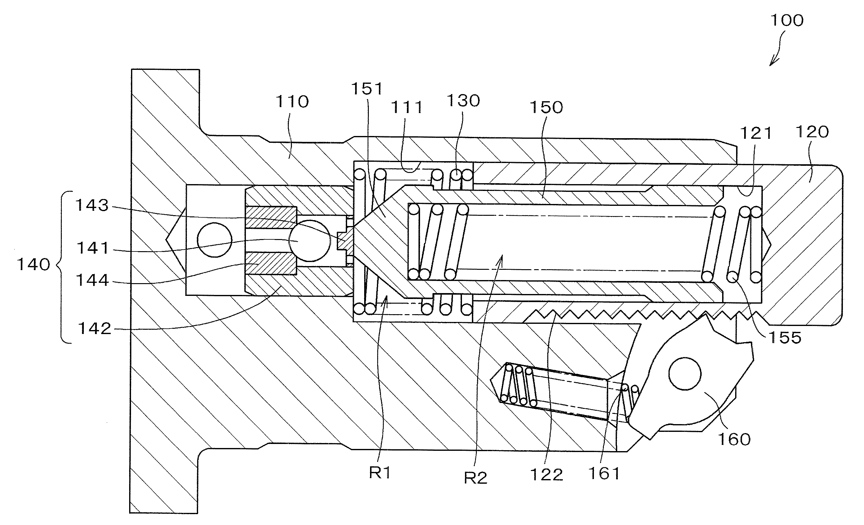
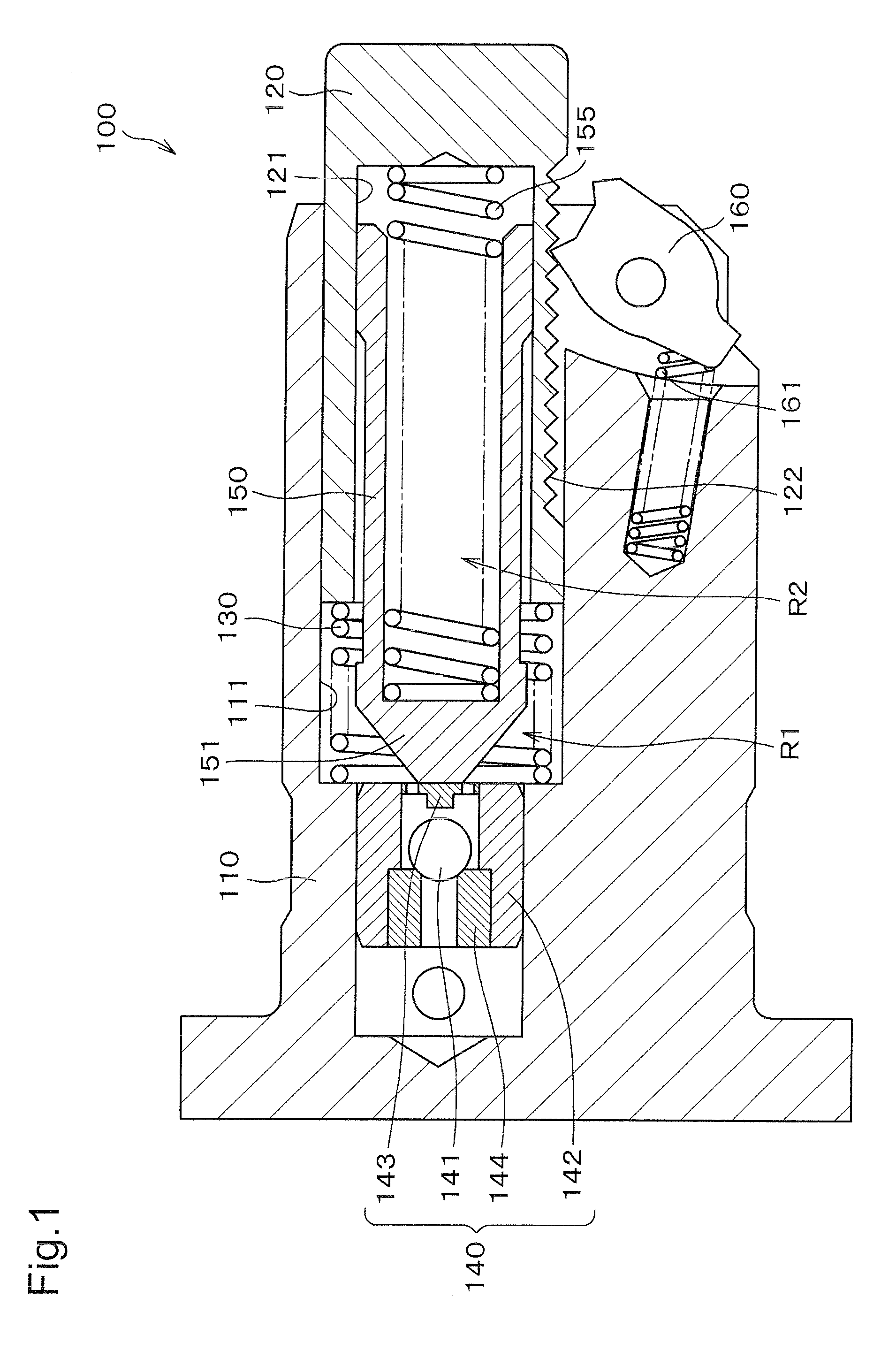
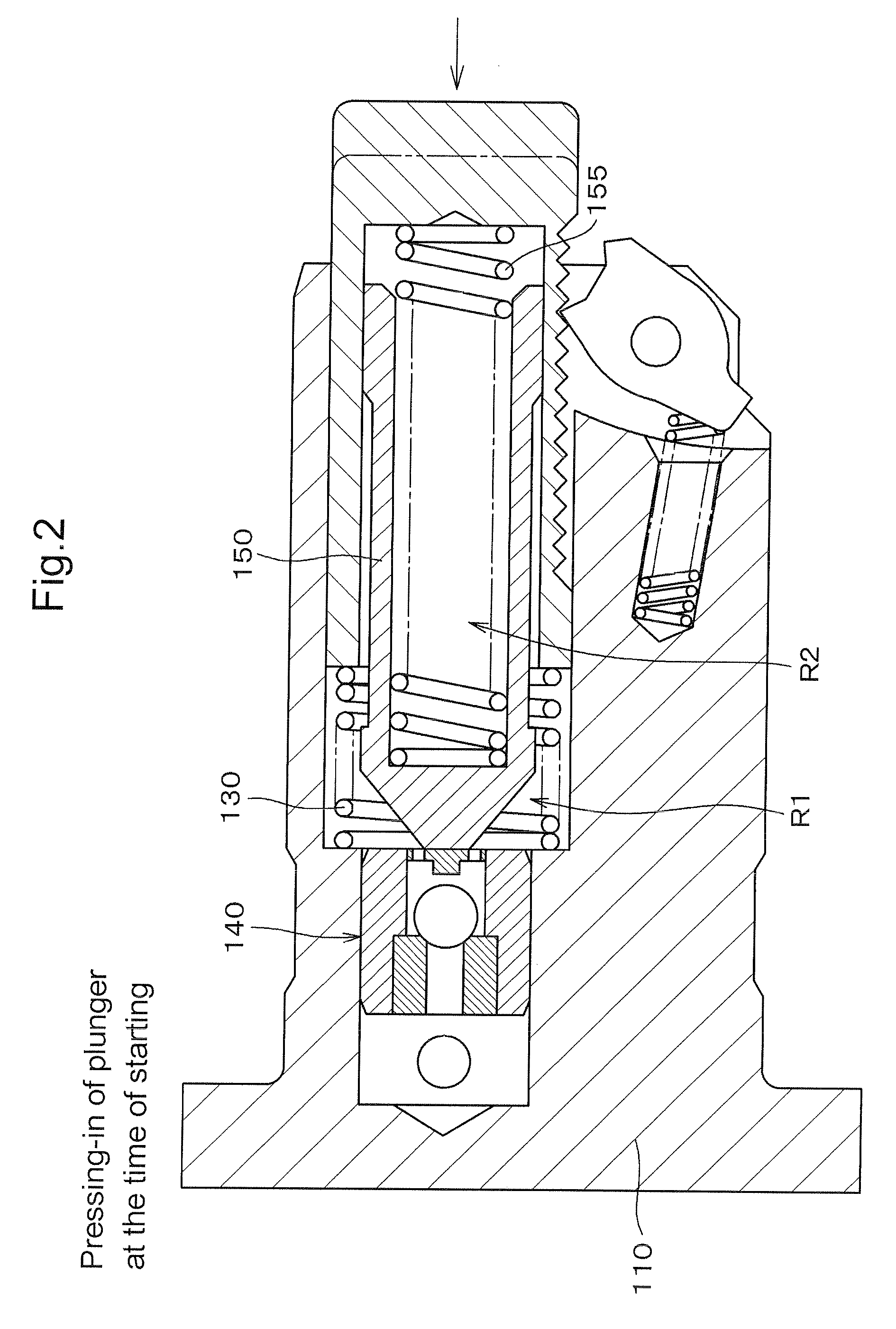
[0033]Briefly, in the hydraulic tensioner according to the invention, an inner sleeve divides the high pressure oil chamber into two parts. During protrusion of the plunger, a negative pressure within a part of the high pressure oil chamber opposes the spring force exerted on the plunger and prevents the pressing force exerted by the plunger from becoming excessive during ordinary operation of the engine.

[0034]The tensioner can utilize any of various types of check valves, and the inner sleeve can be composed of any of various materials, including, for example, a metal such as iron, or a resin or the like.

[0035]As shown in FIG. 1, in a hydraulic tensioner 100, a hollow, cylindrical plunger 120 is slidable in a plunger-accommodating hole 111 formed in a housing 110, and a hollow inner sleeve 150 fits slidably in an inner sleeve accommodating hole 121 formed in the plunger. The hollow plunger has a blind hole having an opening facing toward the bottom of the plunger-accommodating hole...


PUM


Abstract

The hollow plunger of a hydraulic tensioner, slidably receives a sleeve that divides the high pressure oil chamber into two parts. The first part is formed by the plunger and a plunger-accommodating hole of the tensioner housing. The second part is formed by the plunger and the sleeve. Two springs, one being in the first part, and the other being in the second part, urge the plunger in the protruding direction. When the second part is filled with oil during ordinary engine operation, a negative pressure in the second part exerts a force opposing protruding movement of the plunger. Therefore, the springs can be made strong enough to prevent excessive chain vibration and noise during engine start-up when the parts of the high pressure oil chamber are not filled with oil, without causing the tensioner to exert excessive force on the chain during ordinary engine operation.

Description

CROSS-REFERENCE TO RELATED APPLICATION[0001]This application claims priority on the basis of Japanese patent application 2008-035574, filed Feb. 18, 2008. The disclosure of Japanese application 2008-035574 is hereby incorporated by reference.FIELD OF THE INVENTION[0002]The invention relates to a hydraulic tensioner for maintaining proper tension in an endless, flexible, traveling transmission medium such as a timing belt or a timing chain in a vehicle engine.BACKGROUND OF THE INVENTION[0003]Hydraulic tensioners incorporating check valves have been widely used to maintain proper tension, and to suppress vibration, in a timing belts or timing chain used to transmit rotation between a crankshaft and one or more camshafts in a vehicle engine.[0004]As shown in FIG. 7, a conventional hydraulic tensioner 500 is typically mounted on an engine adjacent the slack side of a timing chain C, which is driven by a crankshaft sprocket S1 and in driving relationship with camshaft sprockets S2. A plu...

Claims


Application Information

Patent Timeline
IPC IPC(8): F16H7/08
CPCF16H7/0836F16H7/0848F16H2007/0859F16H2007/0812F16H2007/0853F16H2007/0806F16H7/18F16H7/08
Inventor KUREMATSU, YUJI
Owner TSUBAKIMOTO CHAIN CO
Learn More