
A knife carriage, a rotary veneer lathe having the same, and a veneer slicer having the same

Pending Publication Date: 2022-05-19
MEINAN MASCH WORKS INC
View PDF0 Cites 0 Cited by
  • Summary
  • Abstract
  • Description
  • Claims
  • Application Information

AI Technical Summary

Benefits of technology

The present invention provides a support system for peeling veneer from wood that allows for independent movement of the support system based on the reaction force of a pressing force. This results in a more uniform deformation of the long pressure bar and allows for appropriate pressing force without excessive damage to the veneer. Additionally, the design prevents the accumulation of powdery wood chips at the cutting edge and prevents scratching or staining on the veneer. The quality of the resulting veneer is enhanced.

Problems solved by technology

In other words, when a knife peels a knot part of the log, or when a fragment or chip of the wood (including powdered wood chips) enters the cutting edge, the long pressure bar does not deform uniformly.

Method used


Image

  • A knife carriage, a rotary veneer lathe having the same, and a veneer slicer having the same
  • A knife carriage, a rotary veneer lathe having the same, and a veneer slicer having the same
  • A knife carriage, a rotary veneer lathe having the same, and a veneer slicer having the same

Examples


Embodiment Construction

[0077]Next, the best embodiment for carrying out the present invention will be described using examples.

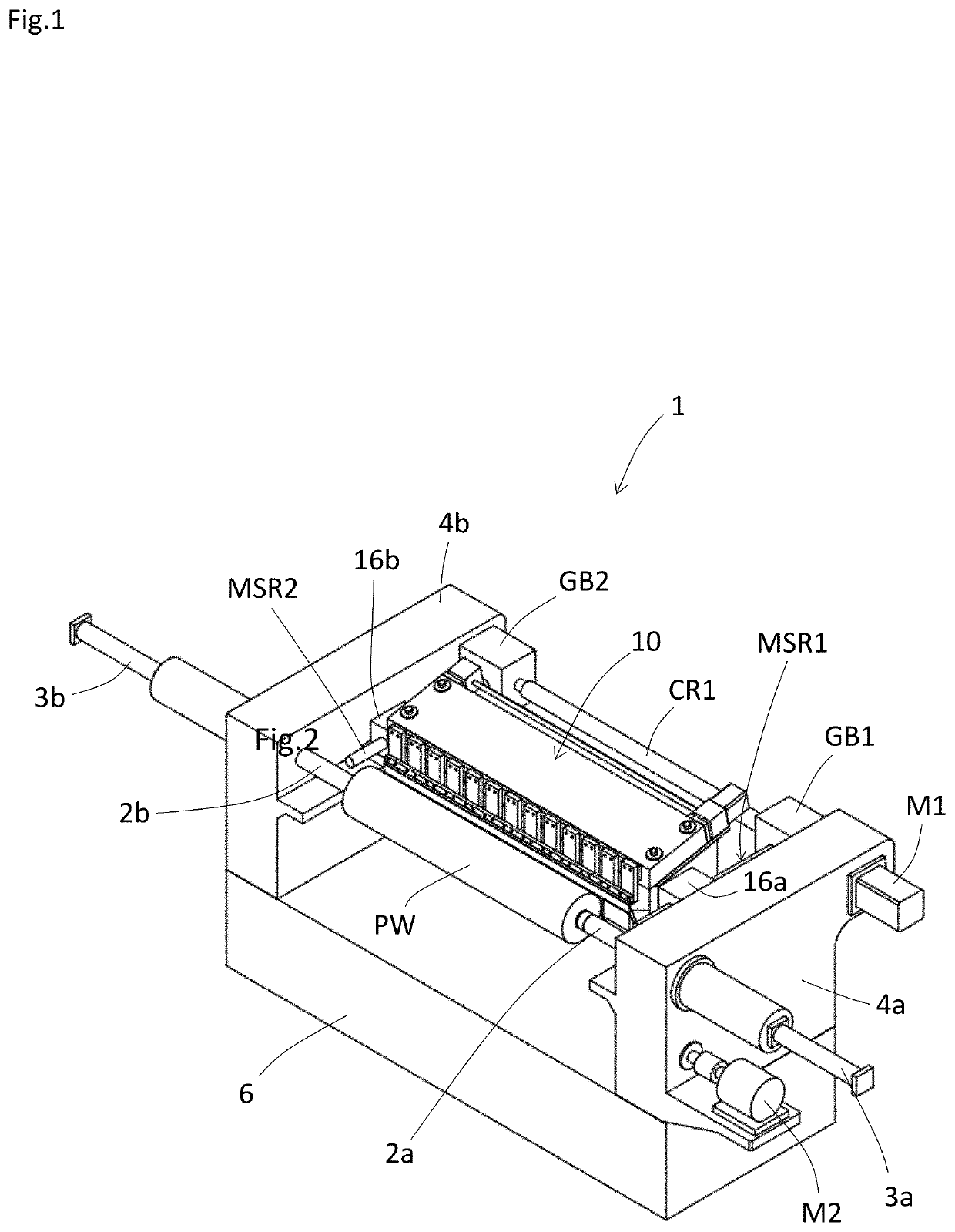
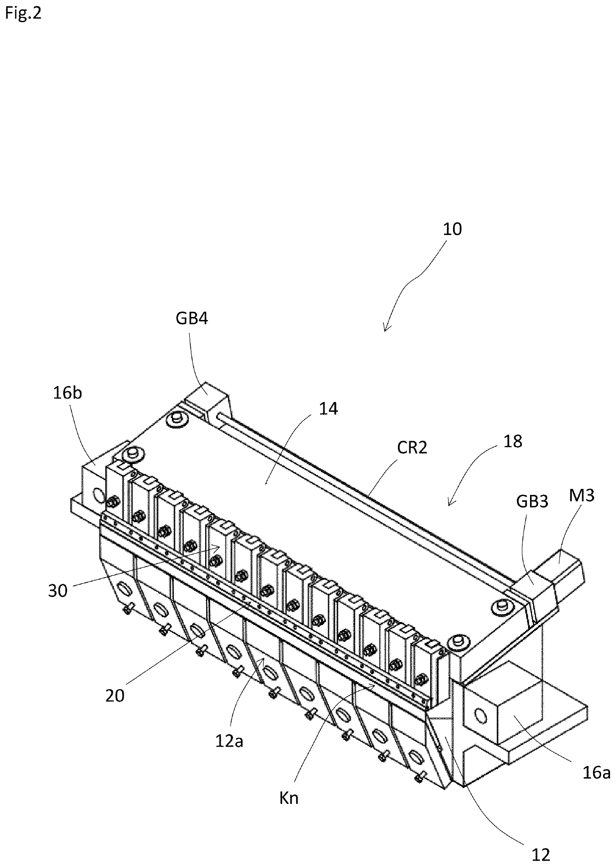
[0078]As shown in FIG. 1, a rotary veneer lathe 1 according to an embodiment of the present invention includes a pair of support frames 4a, 4b having a pair of cutting spindles 2a, 2b, and a base frame 6 for connecting the pair of support frames 4a, 4b, and a knife carriage 10 of an embodiment of the present invention that is disposed between the pair of support frames 4a and 4b and above the base frame 6. The pair of support frames 4a, 4b correspond to “vertical walls” in the present invention, and the base frame 6 is an example of an embodiment corresponding to a “pedestal” in the present invention. The pair of support frames 4a and 4b and the base frame 6 are an example of an embodiment corresponding to the “machine frame” of the present invention.

[0079]As shown in FIG. 1, the pair of cutting spindles 2a and 2b are arranged coaxially and in such a manner that the tips are oppos...


PUM


Abstract

A nosebar is supported by supports arranged along the longitudinal direction, and the supports are assembled to fixtures to swing independently of each other in a direction away from a log according to the reaction force of the pressing force acting on the supports. Thus, when a knife peels a knot part of the log or a fragment of the log enters a cutting edge, the portion of the nosebar pressing the knot part or corresponding to the location where the fragment enters the cutting edge is greatly deformed, while the deformation of the nosebar in the other portions is kept small. A corner of the nosebar is prevented from contacting the peeled portion of the raw wood and generating a gap when the nosebar is bent and deformed.

Description

CROSS-REFERENCE TO RELATED APPLICATIONS[0001]This application is the U.S. National Phase of International Application No. PCT / JP2020 / 025604, filed Jun. 30, 2020, which claims priority to Japanese Patent Application No. 2019-141946, filed Aug. 1, 2019. The contents of both of those applications are incorporated by reference herein in their entirety.TECHNICAL FIELD[0002]The present invention relates to a knife carriage configured to have a long knife arranged in a direction orthogonal to both the axial direction and of a pair of cutting spindles and the vertical direction so as to face a log held between the pair of cutting spindles, the knife being configured so as to peel a veneer from the log held between the pair of cutting spindles. The knife carriage is also configured to have a long pressure bar for pressing a peeled portion of the veneer out of the log from the side opposite to the side where the knife is arranged with respect to the peeled portion. The present invention also ...

Claims


Application Information

Patent Timeline
IPC IPC(8): B27L5/02B27L5/00
CPCB27L5/025B27L5/008B27L5/02B27L5/00
Inventor KOIKE, MASARU
Owner MEINAN MASCH WORKS INC
Learn More