
System, method and apparatus for compensating for drift in a main magnetic field in an MRI system

a main magnetic field and drift compensation technology, applied in the field of magnetic resonance imaging system, can solve problems such as negative impact on image quality

Inactive Publication Date: 2009-08-20
GENERAL ELECTRIC CO
View PDF7 Cites 9 Cited by
  • Summary
  • Abstract
  • Description
  • Claims
  • Application Information

AI Technical Summary

Benefits of technology

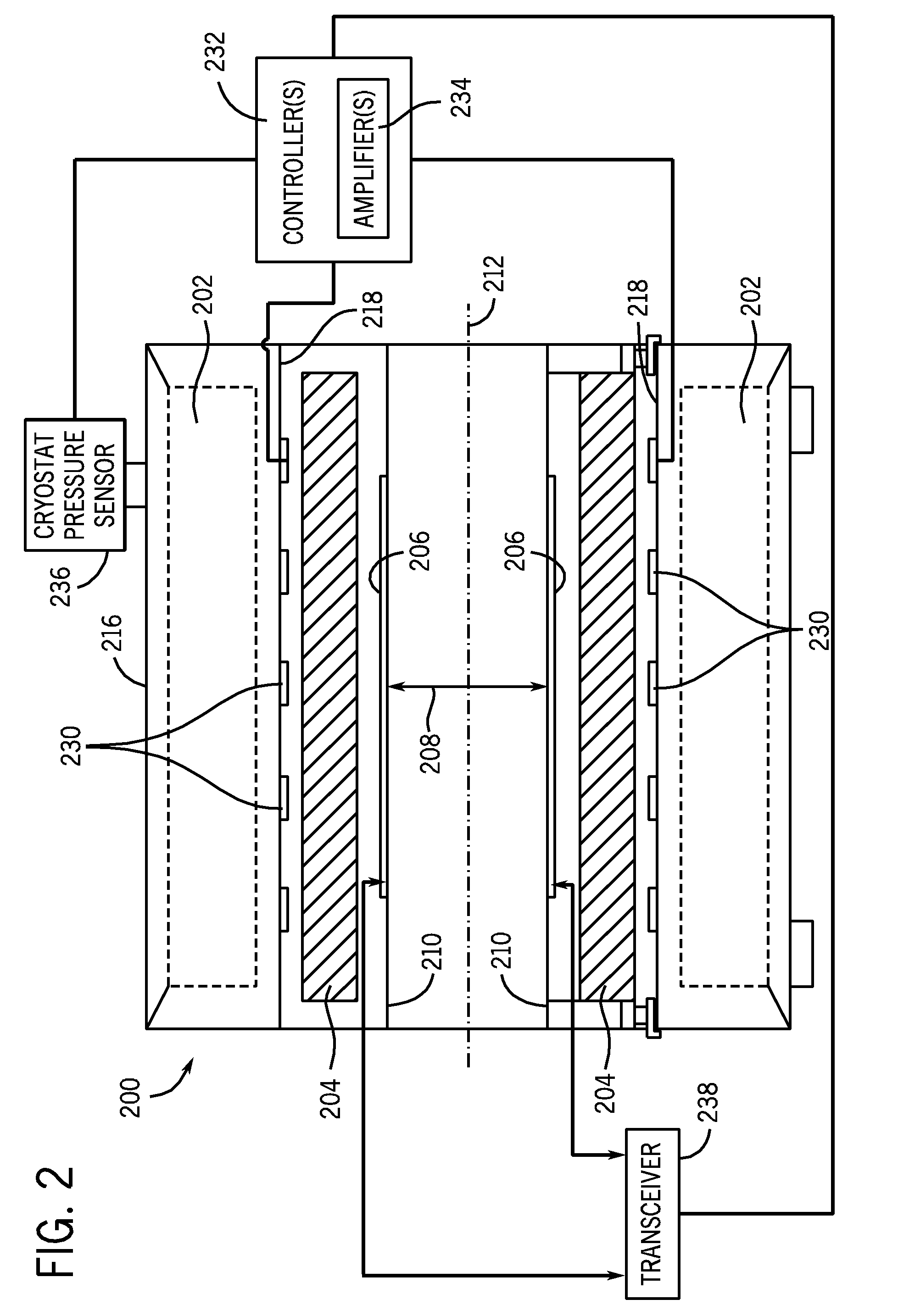
[0006]In accordance with another embodiment, an apparatus for compensating for drift in a main magnetic field of a superconducting magnet in a magnetic resonance imaging (MRI) system includes at least one pressure sensor coupled to a cryostat of the superconducting magnet, the at least one pressure sensor configured to measure a pressure in the cryostat and to generate a pressure signal, at least one shim coil and a controller coupled to the at least one pressure sensor and the at least one shim coil, the controller configured to control the at least one shim coil to provide a compensation field based on at least the pressure signal.
[0007]In accordance with another embodiment, an apparatus for compensating for drift in a main magnetic field of a superconducting magnet in a magnetic resonance imaging (MRI) system includes at least one pressure sensor coupled to a cryostat of the superconducting magnet, the at least one pressure sensor configured to measure a pressure in the cryostat and to generate a pressure signal, a transceiver and a controller coupled to the at least one pressure sensor and the transceiver, the controller configured to control a reference frequency for the transceiver based on at least the pressure signal.

Problems solved by technology

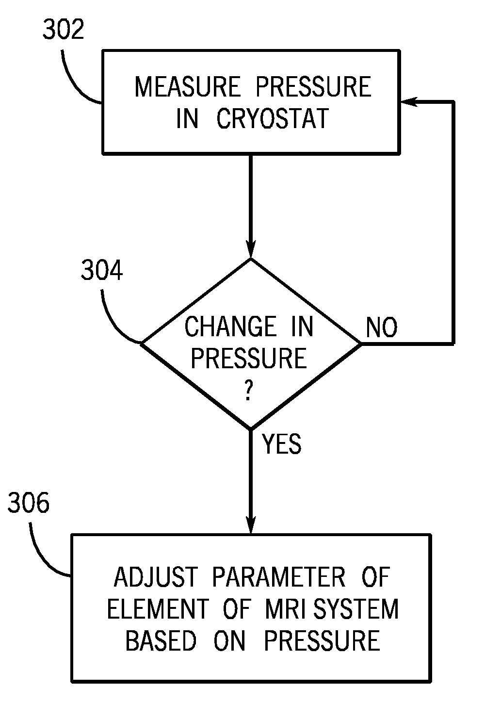
A change in pressure in the cryostat can result in a change or drift in the main magnetic field which in turn can have a negative impact on image quality.

Method used


Image

  • System, method and apparatus for compensating for drift in a main magnetic field in an MRI system
  • System, method and apparatus for compensating for drift in a main magnetic field in an MRI system
  • System, method and apparatus for compensating for drift in a main magnetic field in an MRI system

Examples


Embodiment Construction

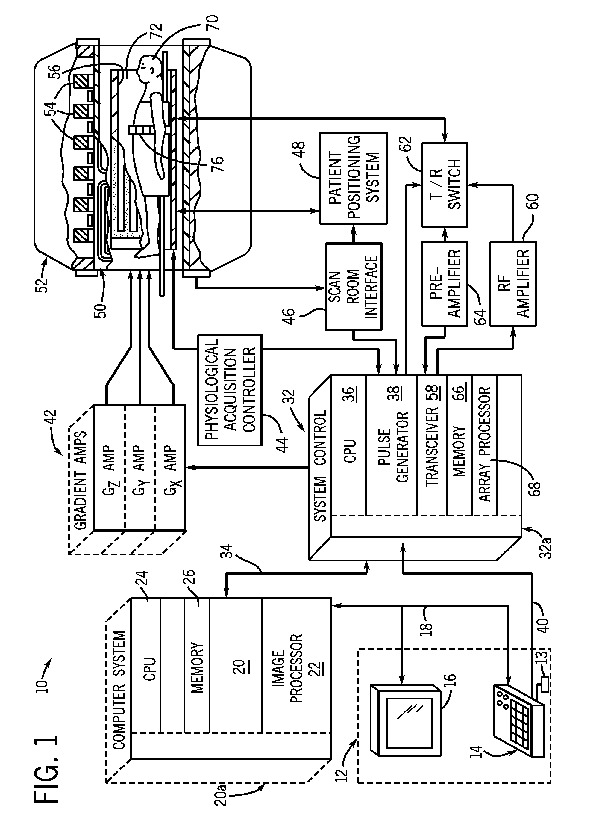
[0015]FIG. 1 is a schematic block diagram of an exemplary magnetic resonance imaging (MRI) system in accordance with an embodiment. The operation of MRI system 10 is controlled from an operator console 12 that includes a keyboard or other input device 13, a control panel 14, and a display 16. The console 12 communicates through a link 18 with a computer system 20 and provides an interface for an operator to prescribe MRI scans, display resultant images, perform image processing on the images, and archive data and images. The computer system 20 includes a number of modules that communicate with each other through electrical and / or data connections, for example, such as are provided by using a backplane 20a. Data connections may be direct wired links or may be fiber optic connections or wireless communication links or the like. The modules of the computer system 20 include an image processor module 22, a CPU module 24 and a memory module 26 which may include a frame buffer for storing...


PUM

PropertyMeasurementUnit
magnetic fieldaaaaaaaaaa
superconductingaaaaaaaaaa
magneticaaaaaaaaaa

Abstract

A method for compensating for drift in a main magnetic field of a superconducting magnet in a magnetic resonance imaging (MRI) system includes measuring a pressure in a cryostat of the superconducting magnet. Based on the pressure, a parameter of an element of the MRI system is adjusted to correct or compensate for a change in the main magnetic field.

Description

FIELD OF THE INVENTION[0001]The present invention relates generally to a magnetic resonance imaging (MRI) system and in particular to a system, method and apparatus for compensating or correcting for drift (or changes) in a main magnetic field, B0, based on a pressure in a cryostat during operation of an MRI system.BACKGROUND OF THE INVENTION[0002]Magnetic resonance imaging (MRI) is a medical imaging modality that can create pictures of the inside of a human body without using x-rays or other ionizing radiation. MRI uses a powerful magnet to create a strong, uniform, static magnetic field (i.e., the “main magnetic field”). When a human body, or part of a human body, is placed in the main magnetic field, the nuclear spins that are associated with the hydrogen nuclei in tissue water become polarized. This means that the magnetic moments that are associated with these spins become preferentially aligned along the direction of the main magnetic field, resulting in a small net tissue mag...

Claims


Application Information

Patent Timeline
Patent Type & Authority Applications(United States)
IPC IPC(8): G01V3/00H01F6/00
CPCG01R33/3815G01R33/389G01R33/3875
Inventor SEEBER, DEREK A.LINZ, ANTON M.
Owner GENERAL ELECTRIC CO
Learn More