
Method for inhibiting amine degradation during c02 capture from a gas stream

a technology of amine degradation and gas stream, which is applied in the direction of hydrogen sulfide, separation process, other chemical processes, etc., can solve the problems of reducing the cosub>2 /sub>absorption capacity, introducing a serious amine degradation problem, and severely affecting the absorption plan

Active Publication Date: 2009-08-20
UNIVERSITY OF REGINA
View PDF13 Cites 34 Cited by
  • Summary
  • Abstract
  • Description
  • Claims
  • Application Information

AI Technical Summary

Benefits of technology

[0013]Other features and advantages of the present application will become apparent from the following detailed description. It should be understood, however, that the detailed description and the specific examples while indicating preferred embodiments of the application are given by way of illustration only, since various changes and modifications within the spirit and scope of the disclosure will become apparent to those skilled in the art from this detailed description.

Problems solved by technology

However, reactive contaminants, specifically O2 and SO2, constantly introduce a serious amine degradation problem during the absorption process.
The degradation severely affects the absorption plant by reducing the CO2 absorption capacity of the amine and inducing corrosion and foaming problems due to accumulation of the degradation products.
The literature has suggested a long-term solution for amine degradation by locating the source of O2.2 However, this approach is highly complicated since a complete removal of O2 as well as SO2 from a major source such as flue gas streams is impractical.
Also, the detection and removal of O2 is especially known to be time-consuming and labor-intensive.3 To maintain the performance of the CO2 absorption process, a quick prevention technique must then be included as one of the operational routines of the absorption unit to immediately cope with the degradation problem.
Unfortunately, the inhibitor / O2 scavenger information was not disclosed in the literature.
However, it had no effect when CO2 was absent from the oxidation system.
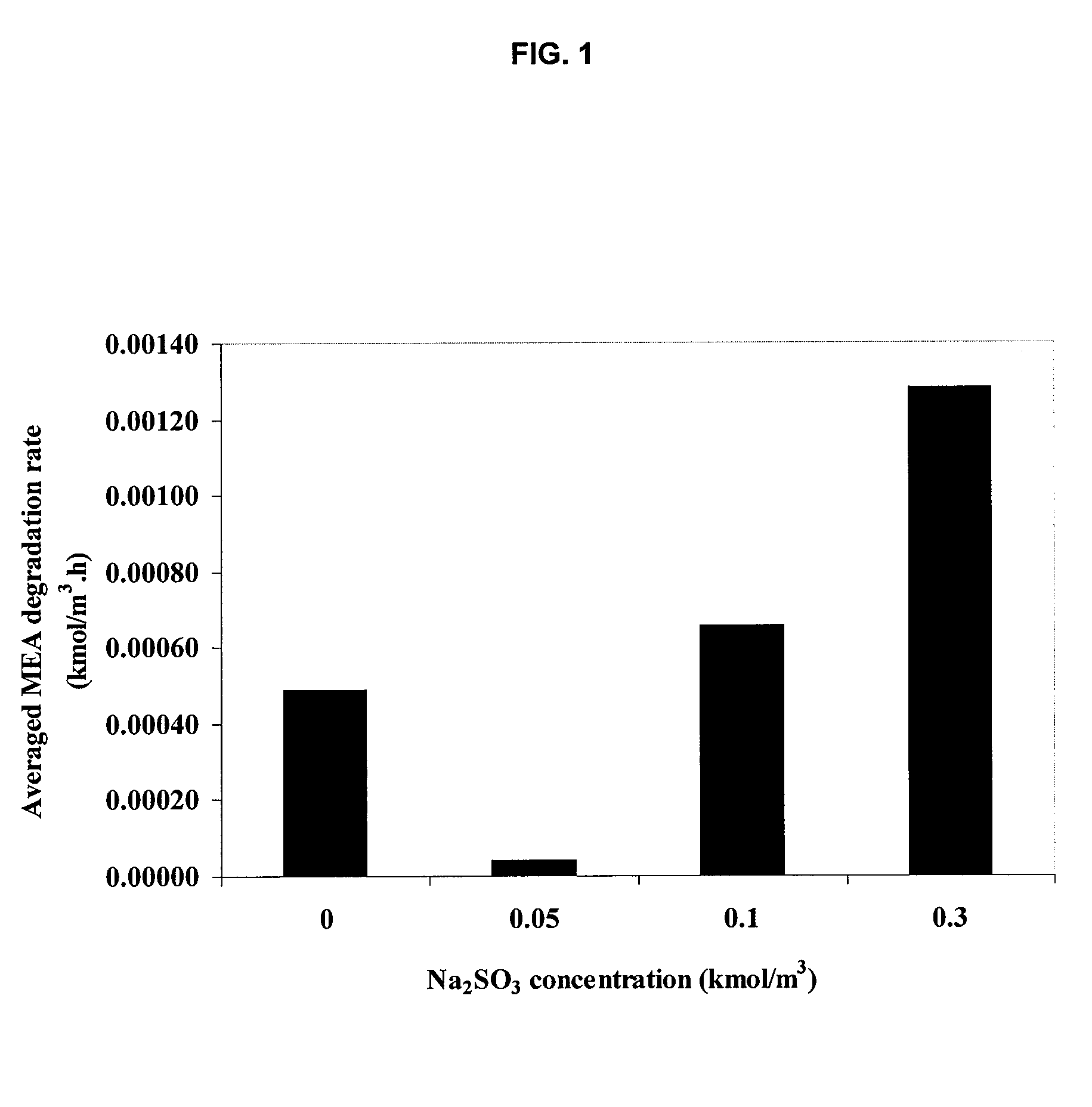
Although, formaldehyde could reduce the degradation rate, it was not as effective as Inhibitor A. Both Na2SO3 and formaldehyde worked more effectively in copper catalyzed environment than iron system.

Method used


Image

  • Method for inhibiting amine degradation during c02 capture from a gas stream
  • Method for inhibiting amine degradation during c02 capture from a gas stream
  • Method for inhibiting amine degradation during c02 capture from a gas stream

Examples


example 1

Non-CO2 Loaded Degradation

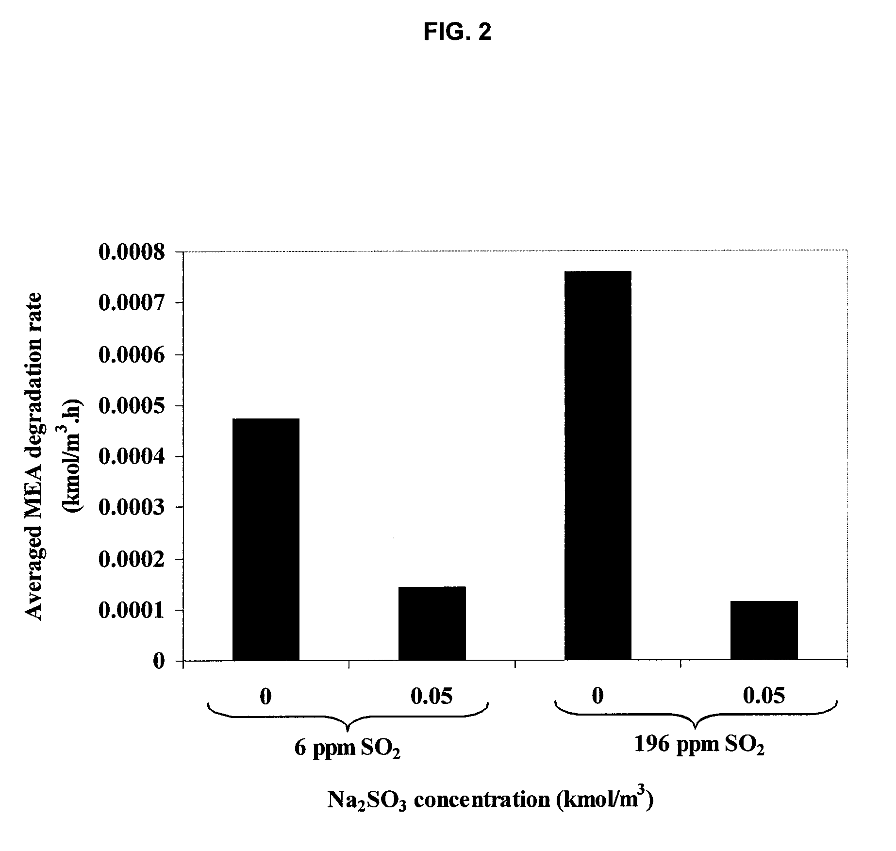
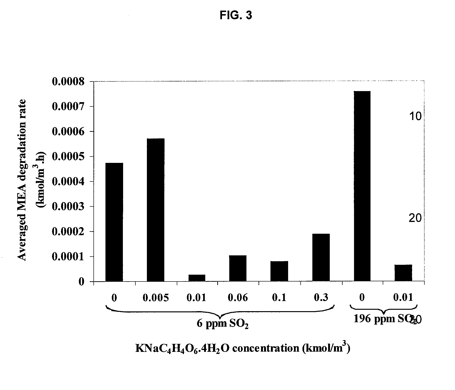
MEA-H2O—O2 with / without SO2

[0049]For a typical run, the reactor vessel was filled with 450 ml of MEA solution spiked with the inhibitors of the desired concentration. The reactor head and the vessel were carefully assembled by tightening the 6 hex-bolts in a criss-cross manner to prevent leakage. The unit was placed in the furnace. The magnetic drive-stirrer was connected to the motor whereas the J-type thermocouple was hooked up to the temperature-speed controller. The solution was heated and stirred throughout the experiment at a constant speed of 500 rpm. Time was given to allow the temperature to reach and stabilize at the set point. At this stage, most pressure inside the reactor only resulted from water vapor pressure as determined by previous studies.8,9,13 This led us to neglect MEA vapor pressure, thus allowing the degradation to be formulated as a homogeneous liquid phase process. Predetermined pressure of the O2 / N2 or O2 / N2 / SO2 gas mixture at 25...

example 2

CO2 Loaded Degradation

MEA-H2O—O2—CO2 with / without SO2

[0050]Once the MEA solution was placed in the vessel and the reactor head was put in place, regulated CO2 pressure of 250 kPa was introduced into the MEA solution by opening its cylinder and gas inlet valve. The time needed to load CO2 varied from 0.25 to 2 h depending on the desired dissolved CO2 concentration in the MEA solution. By opening the liquid sampling valve, 4 ml of sample was taken and measured for CO2 loading using the technique of HCl volumetric titration and CO2 displacement in NaCl / NaHCO3 / methyl orange mixture. This was achieved by titrating a known volume of CO2-loaded MEA sample with excess 1 kmol / m3HCl to ensure complete release of CO2 from MEA. The liberated CO2 was collected and measured for its quantity in the displacement solution and was then expressed in terms of moles of CO2 per one mole of MEA (CO2 loading). The mixture was raised to the desired temperature and final CO2 loading was once again determine...

example 3

HPLC Procedure

[0051]The HPLC procedure for determination of MEA concentration is detailed in the literature.13 In brief, mobile phase containing 0.05 kmol / m3 at pH 2.6 was degassed in an ultrasonic bath for 3 hours and filtered by a 0.20 μm nylon membrane filter to respectively remove dissolved O2 and solid particles. Prior to injection, degraded sample was diluted with 1 in 40 ratio using nanopure water followed by filtration with 0.20 μm nylon membrane filter. Sample injection of 8 μl was done automatically by the automatic liquid sampler as described previously. The column was controlled isothermically at 303 K. Isocratic mode of 1 ml / min mobile phase was used throughout to achieve the analysis. RID used to detect MEA peak was also controlled at 303 K for its optical unit and operated in the positive mode.


PUM

PropertyMeasurementUnit
molar ratioaaaaaaaaaa

Abstract

The present application includes a method for inhibiting amine degradation during CO2 capture from flue gas streams. Particularly, the present disclosure relates to a method of inhibiting O2- and / or SO2-induced degradation of amines using sodium sulfite (Na2SO3), potassium sodium tartrate tetrahydrate (KNaC4H4O6.4H2O), ethylenediaminetetraacetic acid (EDTA) or hydroxylamine (NH2OH), or analogs or mixtures thereof during CO2 capture by amines.

Description

FIELD OF THE DISCLOSURE[0001]The present application relates to a method for inhibiting amine degradation during carbon dioxide (CO2) capture from a gas stream. Particularly, the present disclosure relates to a method of inhibiting oxygen- (O2) and / or sulfur dioxide- (SO2) induced degradation of amines using sodium sulfite (Na2SO3), potassium sodium tartrate tetrahydrate (KNaC4H4O6.4H2O), ethylenediaminetetraacetic acid (EDTA) or hydroxylamine (NH2OH), or analogs thereof or mixtures thereof.BACKGROUND[0002]The composition of fossil fuel-derived flue gases is commonly made up of carbon dioxide (CO2), nitrogen (N2), oxygen (O2), sulfur dioxide (SO2), nitrogen dioxide (NO2), and fly ash of inorganic oxides such as SiO2, Al2O3, Fe2O3, CaO, MgO, Na2O, K2O and P2O5.1 In order to comply with environmental regulations, the flue gas streams must be treated prior to atmospheric discharge to remove CO2 known as a major greenhouse gas. Absorption via chemical reactions using aqueous amine solut...

Claims


Application Information

Patent Timeline
Patent Type & Authority Applications(United States)
IPC IPC(8): B01D47/00C09K3/00
CPCB01D53/1493B01D2251/206B01D2251/304B01D2251/306B01D2251/902Y02C10/06B01D2252/20421B01D2252/20484B01D2252/604B01D2257/504Y02C10/04B01D2252/20405Y02C20/40
Inventor IDEM, RAPHAELTONTIWACHWUTHIKUL, PAITOONSAIWAN, CHINTANASUPAP, TEERADETPITIPUECH, PURACHET
Owner UNIVERSITY OF REGINA
Learn More