Vehicle door handle device
a technology for a door handle and a vehicle, which is applied in the direction of mechanical control devices, keyhole guards, instruments, etc., can solve the problems of deterioration of the inside and affecting the safety of the cylinder lock
- Summary
- Abstract
- Description
- Claims
- Application Information
AI Technical Summary
Benefits of technology
Problems solved by technology
Method used
Image


Examples
first embodiment
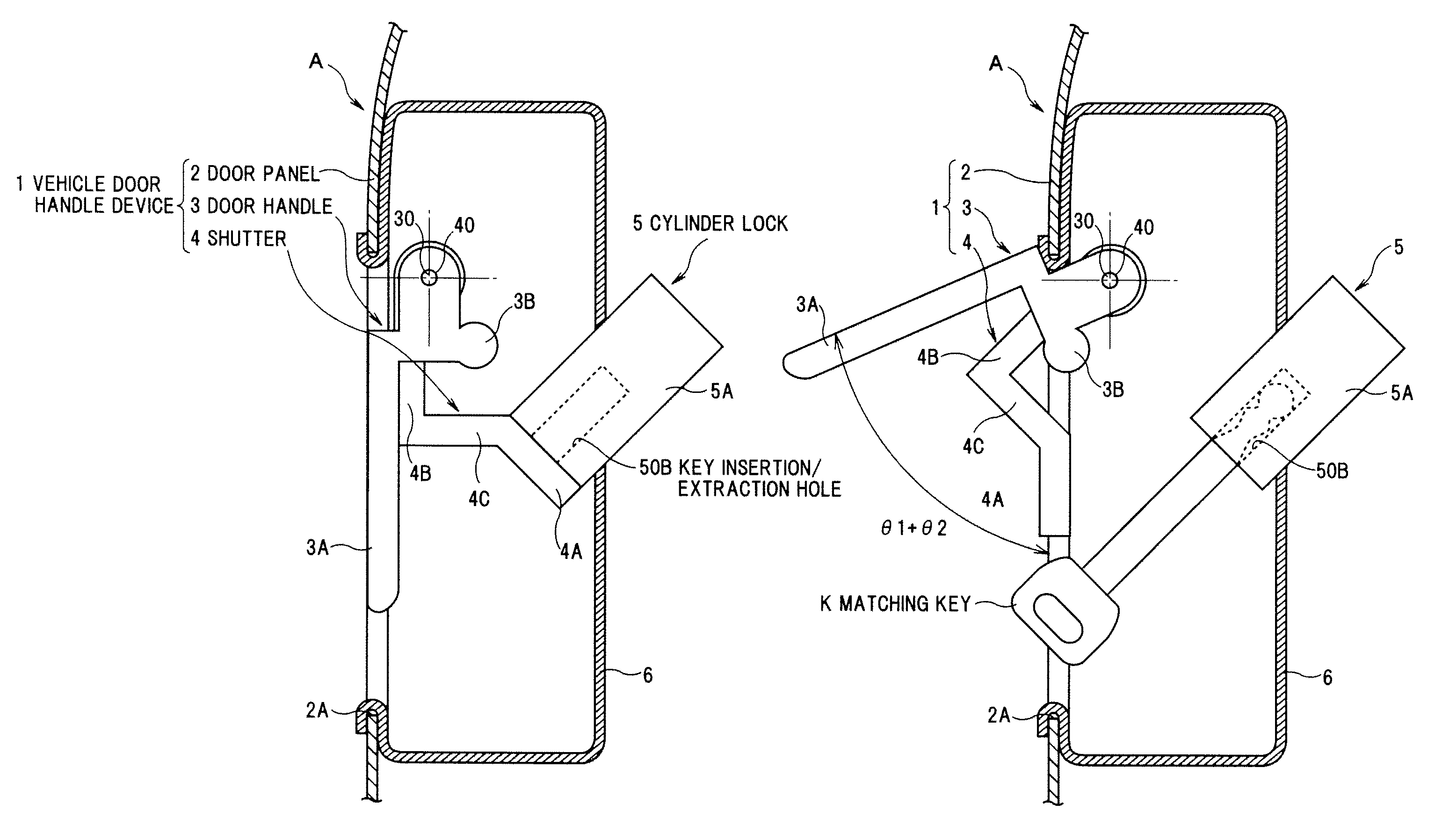
[0044]FIG. 1 is a perspective view showing a vehicle with a built-in vehicle door handle device in a first preferred embodiment of the invention. FIG. 2 is an explanatory cross sectional view showing the vehicle door handle device in the first embodiment of the invention. FIG. 3 is a cross sectional view showing a state that a matching key is inserted into a cylinder lock of the vehicle door handle device in the first embodiment of the invention.
Total Structure of a Vehicle Door Handle Device
[0045]In FIGS. 1 and 2, a vehicle door handle device 1 is composed of a door panel (opening / closing panel) 2 for opening and closing a external door of a vehicle A, a door handle (another pivot member) 3 for operating the door panel 2, and a shutter (one pivot member) 4 having a pivot fulcrum 40 on an axis line passing through a pivot fulcrum 30 of the door handle 3.
Structure of the Door Panel 2
[0046]As shown in FIG. 2, the door panel 2 has a cylinder lock 5 for locking and unlocking a door lock...
second embodiment
[0067]FIG. 6 is an explanatory cross sectional view showing a vehicle door handle device in a second preferred embodiment of the invention. In FIG. 6, the members same as or equivalent to FIG. 2 are given the same reference numbers and the explanation will be omitted.
[0068]As shown in FIG. 6, a vehicle door handle device 61 in the second embodiment is characterized in that a shutter 62 as one pivot member is composed of a first arm 62A and a second arm 62B.
[0069]Therefore, a shutter portion 620A for opening and closing the key insertion / extraction hole 50B of the cylinder lock 5 (the key rotor 50) is provided on the first arm 62A, and a pivotal force receiving portion 620B corresponding the pivotal force transmitting portion (cam portion) 3B of the door handle 3 is provided on the second arm 62B, respectively.
[0070]A pivot fulcrum 620 of the shutter 62 located on an axis line parallel to an axis line passing through the pivot fulcrum 30 of the door handle 3 is arranged between the f...
third embodiment
[0080]FIG. 9 is an explanatory cross sectional view showing a vehicle door handle device in a third preferred embodiment of the invention. In FIG. 9, the members same as or equivalent to FIG. 2 are given the same reference numbers and the explanation will be omitted.
[0081]As shown in FIG. 9, a vehicle door handle device 11 in the third embodiment is characterized in that a door handle (operating handle) 30 having a shutter portion (shutter) 30C for opening and closing the key insertion / extraction hole 50B of the cylinder lock 5 by a pivotal operation is provided.
[0082]Therefore, as shown in FIG. 9, the door handle 30 has a distal end 30A and an operating portion 30B in addition to the shutter portion 30C, is pivotally installed to the door panel 2 via the handle bracket 6, and a restoring property is imparted thereto by a handle pivotal restoring spring (not shown). The door handle 30 is allowed to be pivotally operated with respect to the door panel 2 within a predetermined pivotin...
PUM
 Abstract
Description
Claims
Application Information
 - R&D
- Intellectual Property
- Life Sciences
- Materials
- Tech Scout
- Unparalleled Data Quality
- Higher Quality Content
- 60% Fewer Hallucinations
Browse by: Latest US Patents, China's latest patents, Technical Efficacy Thesaurus, Application Domain, Technology Topic, Popular Technical Reports.
© 2025 PatSnap. All rights reserved.Legal|Privacy policy|Modern Slavery Act Transparency Statement|Sitemap|About US| Contact US: help@patsnap.com