
Compact Exhaust Gas Aftertreatment System

a technology of exhaust gas aftertreatment and exhaust gas, which is applied in the direction of exhaust treatment, mechanical equipment, engine components, etc., can solve the problems of difficult to apportion the reductant in quantity, increase the back pressure of exhaust gas, and difficult to reduce nitrogen oxide using the scr method in internal combustion engines operating in vehicles, so as to avoid the pitfalls of known arrangements

Active Publication Date: 2009-08-20
MAN TRUCK & BUS AG
View PDF19 Cites 17 Cited by
  • Summary
  • Abstract
  • Description
  • Claims
  • Application Information

AI Technical Summary

Benefits of technology

The invention is about arranging an exhaust gas aftertreatment system for internal combustion engines in a way that saves space and avoids the pitfalls of existing arrangements. The invention proposes a system where the existing installation space is used for multiple purposes by integrating different components into the exhaust gas train of the engine. This is particularly useful because catalyzers are often installed close to the engine and can be used for multiple purposes. The invention also integrates different types of catalyzers, such as three-way catalyzers, NOx storage catalyzers, SCR catalyzers, and others. The integration of these catalyzers can be done in a compensator, which is a bellows or corrugated hose or sliding sleeve. The system makes it possible to convert nitrogen oxides into harmless compounds or reclaim them in subsequent reactions. The invention also includes an oxidation catalyzer that can oxidize ammonia and carbon monoxide and hydrocarbons in the exhaust gas. This helps to protect the parts of the engine that come into contact with the exhaust gas from corrosion. Overall, the invention provides a space-saving solution for exhaust gas aftertreatment that avoids the pitfalls of existing arrangements.

Problems solved by technology

Nitrogen oxide reduction using the SCR method in internal combustion engines operating in vehicles is difficult because of the changing operating conditions, which makes it difficult to apportion the reductant in terms of quantity.
Further, the use of V2O5 as active material for the SCR catalyzer leads to problems when the exhaust gas temperature at the SCR catalyzer exceeds 650° C. because the V2O5 is sublimated.
Due to this difference, particle filters are subject to clogging, which increases the exhaust gas back pressure and lowers engine performance.
A disadvantage in this arrangement is that the nitrogen dioxide generated in the oxidation catalyzer is substantially completely consumed by the selective catalytic reduction in the SCR catalyzer; that is, it is no longer available for the conversion of the solids particles that have accumulated in the particle filter arranged downstream.
Therefore, the regeneration of the particle filter must be carried out uneconomically through cyclical heating of the exhaust gas flow by enriching the exhaust gas flow with unconsumed hydrocarbons.
On the one hand, an arrangement of this kind for regenerating the particle filter is elaborate and therefore expensive.
On the other hand, the cyclical regeneration of the particle filter situated at the end of the arrangement produces harmful substances again which can no longer be removed from the exhaust gas.
Further, when particle filters are used, the filters can be clogged by engine oil ashes so that these filters must routinely be removed and cleaned.
While the arrangement described above allows a continuous conversion of the soot-type solid particles deposited in the solids filter by means of the nitrogen dioxide generated in the oxidation catalyzer, it has a serious drawback.
leading to clogging of the SCR catalyzer downstream.
However, removing the partial exhaust gas flow close to the engine and metering the reductant leads to a problem.
This can lead to corrosion of the materials installed in the engine block, particularly the seals.
However, an additional catalyzer would exacerbate the problem of space which already exists due to the number of catalyzers that are used, the reductant injection system and the particle separators, because there is often insufficient installation space available particularly in internal combustion engines installed in vehicles.

Method used


Image

  • Compact Exhaust Gas Aftertreatment System
  • Compact Exhaust Gas Aftertreatment System
  • Compact Exhaust Gas Aftertreatment System

Examples


Embodiment Construction

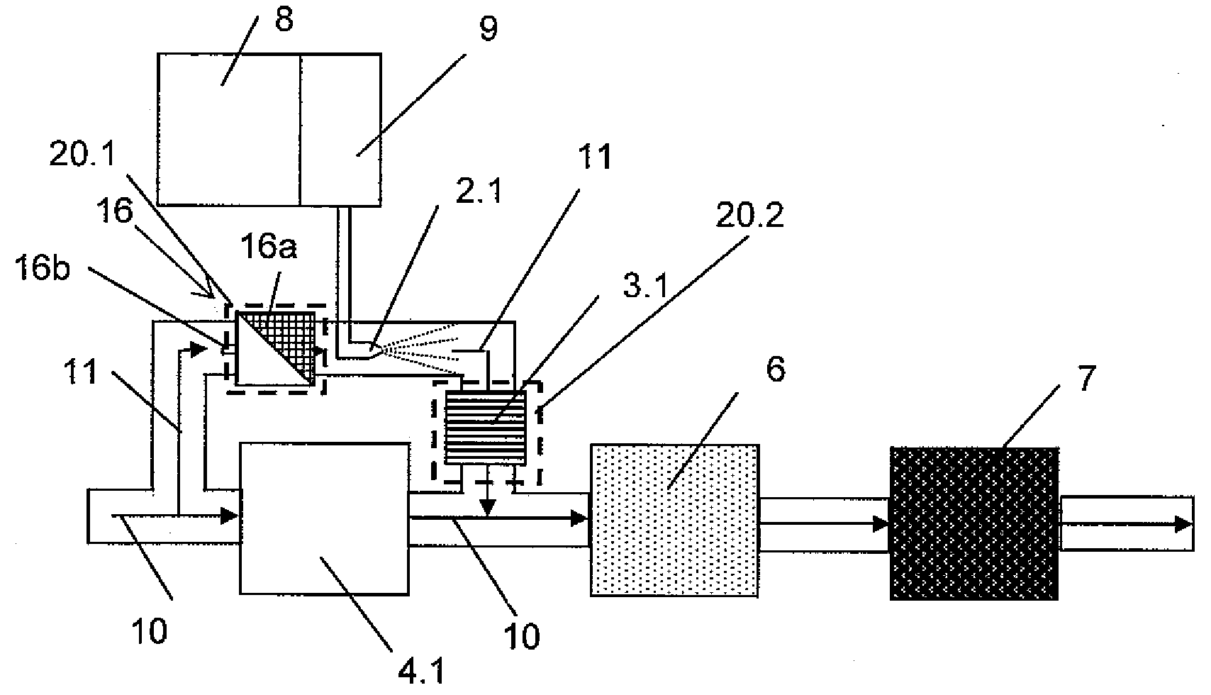
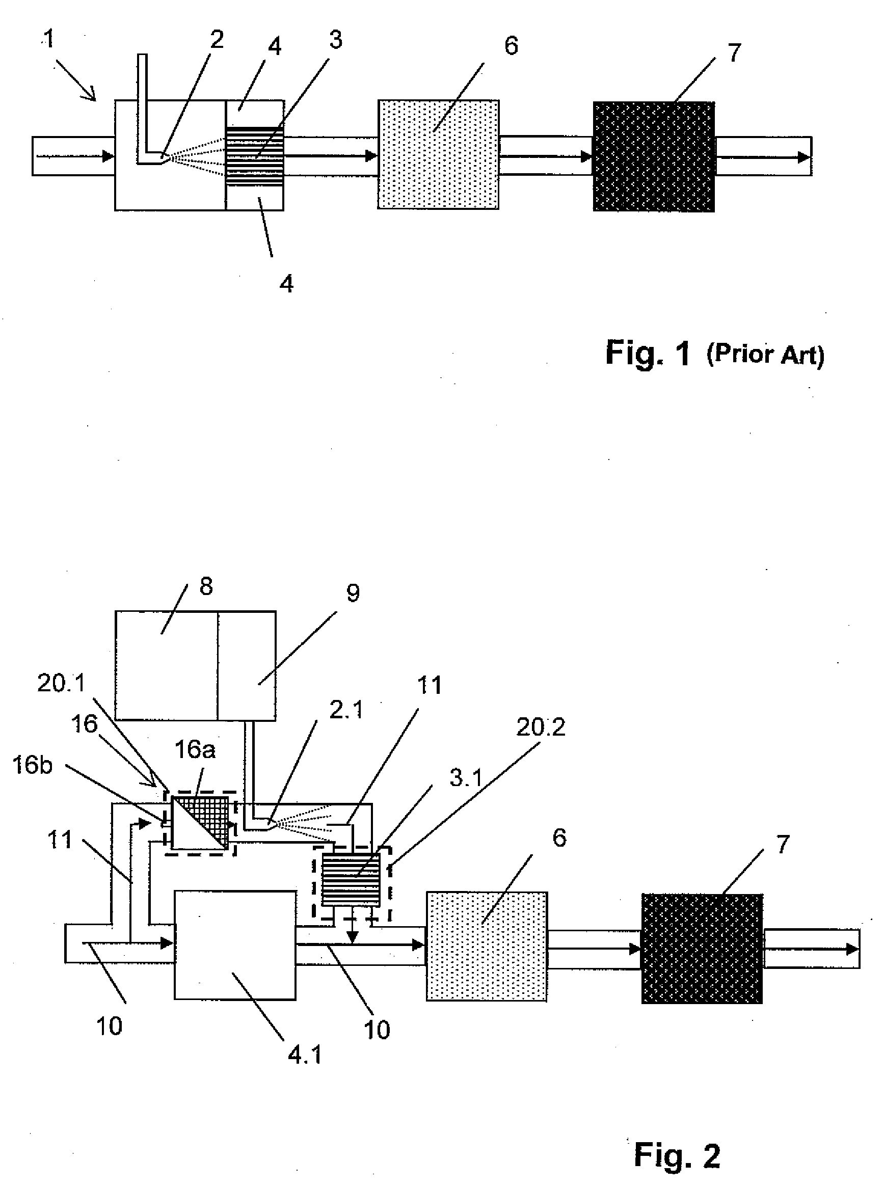
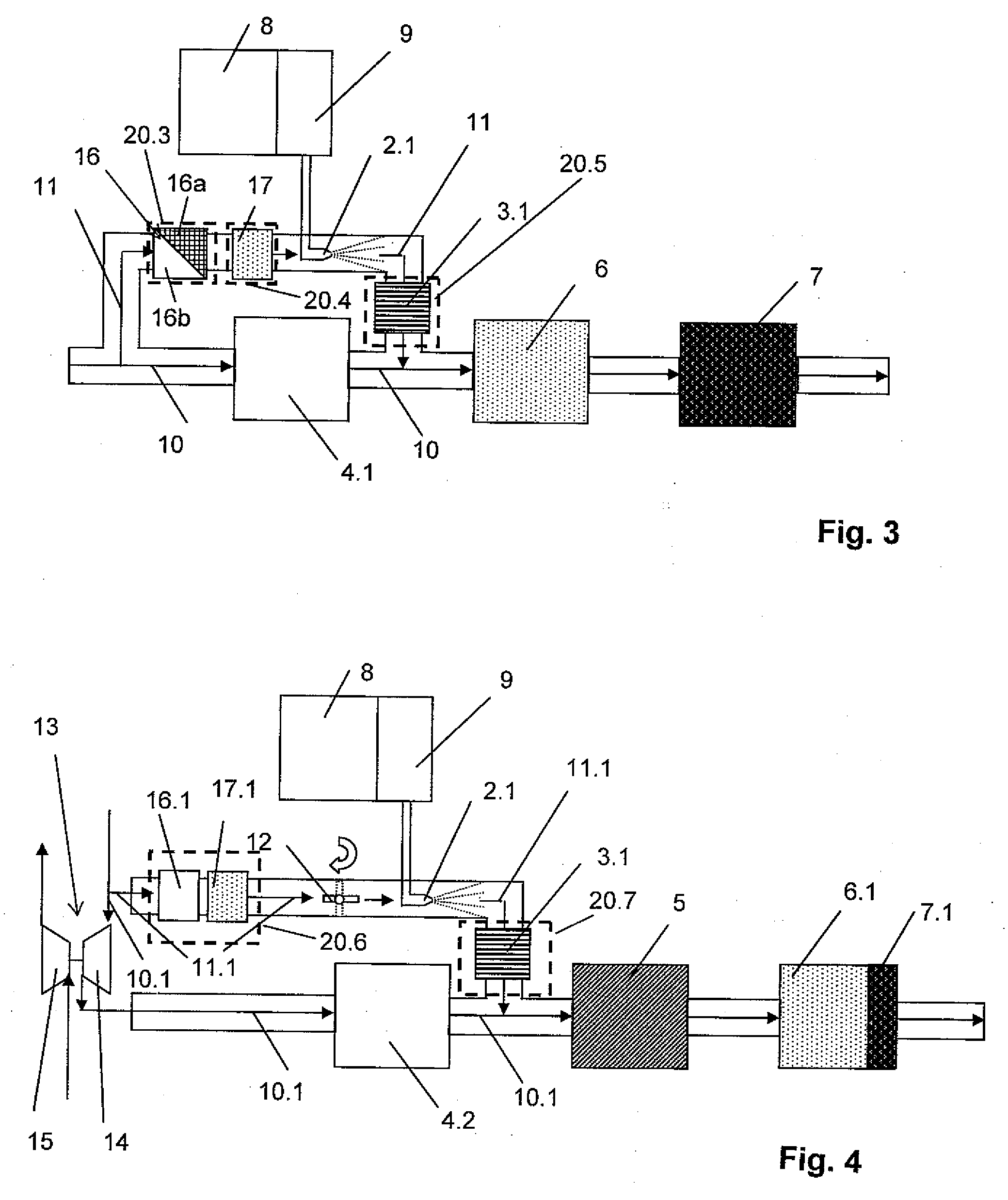
[0067]First, for purposes of background, a prior art arrangement for removing nitrogen oxides from the exhaust gas in an internal combustion engine by means of selective catalytic reduction is shown schematically in FIG. 1.

[0068]The exhaust gases, represented by arrows in FIG. 1, generated by an internal combustion engine (not shown) through combustion processes initially reaches an exhaust gas processing train 1 in which a reductant is added to the hot exhaust gas as close to the engine as possible. As is customary in practice in motor vehicles with SCR catalyzers, the reductant is an aqueous urea solution. Of course, urea can be added in solid form as has already been thoroughly described in the pertinent technical literature. Further, it is possible to add, as a reductant, ammonia which is obtained from another location, e.g., under favorable thermal conditions, from a substance which splits off ammonia. Metering is carried out depending on the operating parameters of the interna...


PUM


Abstract

The invention is directed to a device for converting exhaust gas constituents of an internal combustion engine by means of at least one catalyzer and / or particle filter and / or particle separator and for compensating relative movements between the internal combustion engine and the exhaust gas train and / or relative movements between different parts of the exhaust gas train by means of at least one compensator permitting relative movements. The at least one catalyzer for converting exhaust gas constituents and / or the at least one particle filter and / or the at least one particle separator are / is arranged inside the compensator and or inside the part of the exhaust gas train that is permanently connected to the compensator. The outer diameter of the catalyzer and / or of the particle filter and / or of the particle separator is less than or equal to the inner diameter of the compensator.

Description

BACKGROUND OF THE INVENTION[0001]1. Field of the Invention[0002]The subject matter of the invention is a device for converting exhaust gas constituents of an internal combustion engine by means of at least one catalyzer and / or particle filter and / or particle separator and for compensating relative movements between the internal combustion engine and the exhaust gas train and / or relative movements between different parts of the exhaust gas train by means of at least one compensator permitting relative movements.[0003]2. Description of the Related Art[0004]Due to increasingly stricter limits on exhaust gas which can no longer be met entirely through measures undertaken in the engine, most internal combustion engines have been outfitted in the meantime with aftertreatment systems for reducing harmful emissions.Examples of such aftertreatment systems include[0005]three-way catalyzers[0006]NOx storage catalyzers[0007]diesel oxidation catalyzers[0008]SCR catalyzers[0009]particle filters.[...

Claims


Application Information

Patent Timeline
Patent Type & Authority Applications(United States)
IPC IPC(8): F01N3/035F01N13/08F01N13/18
CPCF01N3/035F01N13/009F01N3/106F01N3/2053F01N3/2066F01N3/28F01N13/1811F01N13/1816F01N2240/40F01N2410/00F01N2410/12F01N2610/02F02B37/18Y02T10/144Y02T10/22Y02T10/24F01N3/101Y02T10/12
Inventor KISTNER, ANDREASDORING, ANDREAS
Owner MAN TRUCK & BUS AG
Learn More