
Method of operating a linear ion trap to provide low pressure short time high amplitude excitation with pulsed pressure

a linear ion trap and pulse pressure technology, applied in the direction of spectrometer combinations, isotope separation, particle separator tubes, etc., can solve the problems of fragmentation of ions, insufficient amplitude, and inability to provide low pressure short time high amplitude excitation, so as to reduce the q reduce the mathieu stability q parameter, and reduce the amplitude of the rf trapping potential

Active Publication Date: 2009-08-06
MDS ANALYTICAL TECH A BUSINESS UNIT OF MDS +1
View PDF5 Cites 47 Cited by
  • Summary
  • Abstract
  • Description
  • Claims
  • Application Information

AI Technical Summary

Benefits of technology

[0007]In various embodiments, the ion trap comprises a quadrupole linear ion trap, having rods (radial electrodes) with substantially circular cross-sections that can produce ion-trapping fields having nonlinear retarding potentials. In various embodiments, the substantially circular cross-section electrodes facilitate reducing losses of ions due to collisions with the electrodes through a dephasing of the trapping RF field and the ion motion.
[0013]In various embodiments, methods are provided for increasing the retention of low-mass fragments of the parent ion after termination of the excitation potential. In various embodiments, after termination of the excitation potential, the q value of the trapping alternating potential (trapping RF) is lowered. The reduction of the q of the RF trapping potential can be reduced to allow the remaining hot (excited) parent ions to continue dissociating, and to retain more of the low-mass fragments. A reduction of the Mathieu stability q parameter can be accomplished by reducing the RF trapping potential amplitude and / or increasing the angular frequency of the RF trapping potential. In various embodiments, these methods facilitate extending the mass range of the fragmentation spectrum towards lower mass values. In various embodiments, q is reduced by at least 10% and sometimes by at least 30% or 60%.
[0014]In various embodiments, methods of the present invention can increase the range of ion fragment masses retained in the ion trap by reducing the value of q after initial excitation of the parent ion. For example, a parent ion can be excited initially with a q value of qexc followed by a reduction in q to a value of qh. The value qh can be determined experimentally as the high-mass cut-off value of q for the parent ion, i.e. the lowest value of q that may be used and still retain the parent ion in the trap. The lowering of the q value results in a percentage increase A % of the range of ion fragment masses retained in the ion trap by the amountΔ%=100×(qexc-qh)(0.908-qexc)(2)where the percentage increase is expressed in relation to the initial range of ion fragment masses retained in the trap, i.e. m−LMCO.
[0015]In various embodiments, methods are provided for increasing the retention of low-mass fragments of the parent ion after termination of the excitation potential. In various embodiments, after termination of the excitation potential and termination of neutral gas delivery, the pressure in the trap is reduced and the q value of the trapping alternating potential (trapping RF) is lowered. The reduction of pressure increases the mean time between collisions, thus providing more time for internally “hot” ions to fragment. With the reduced thermalization rates the timescale for fragmentation after the excitation is turned off can be extended several milliseconds or more. In various embodiments, the q of the RF trapping potential can be reduced to allow the remaining hot parent ions to continue dissociating, and to retain more of the low-mass fragments. The Mathieu stability q parameter can be reduced by reducing the RF trapping potential amplitude and / or increasing the angular frequency of the RF trapping potential. In various embodiments, these methods facilitate extending the mass range of the fragmentation spectrum towards lower mass values.
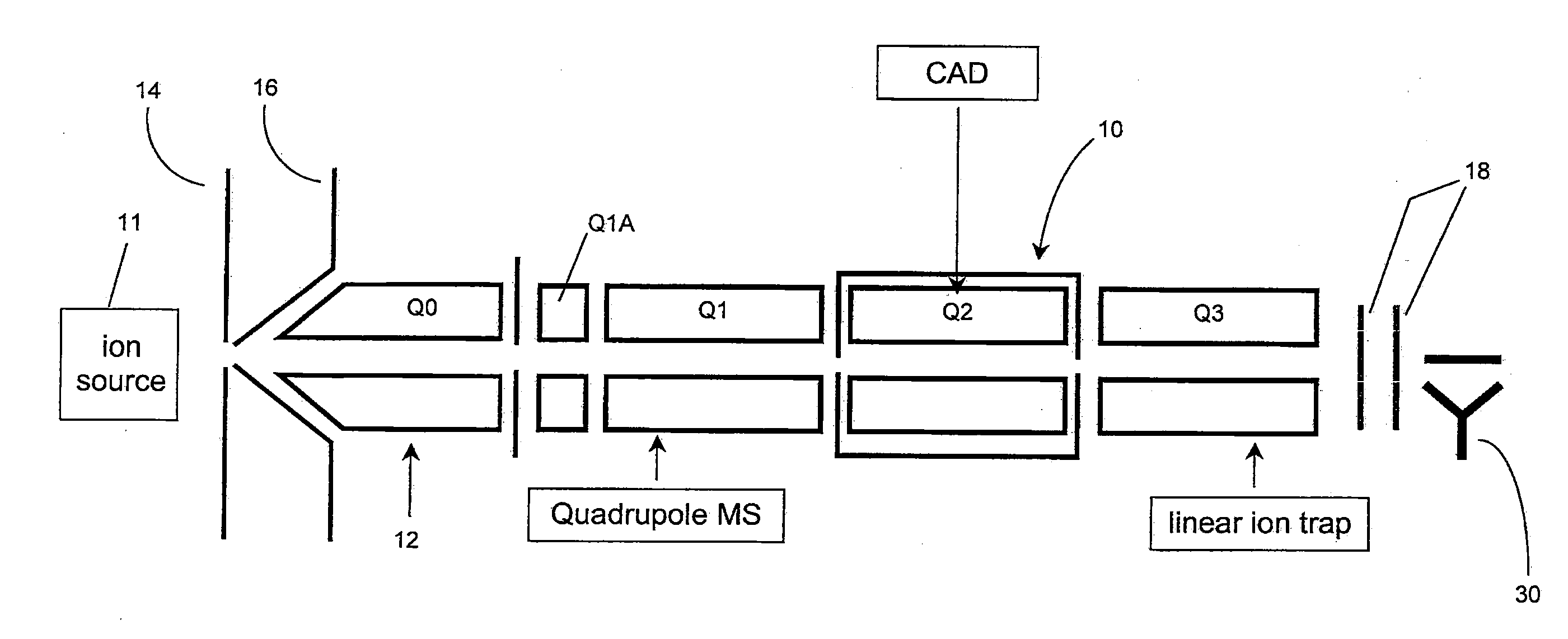
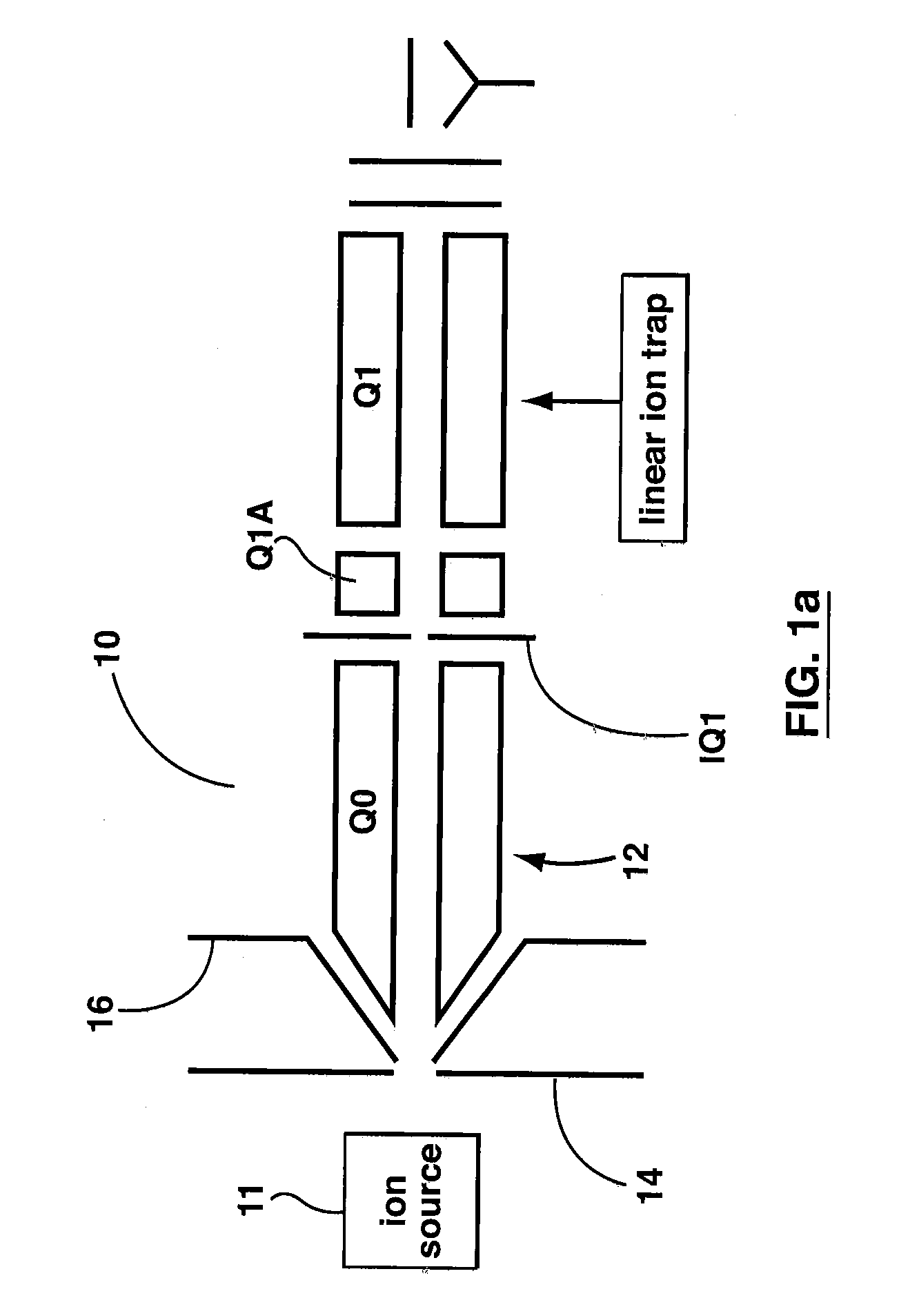
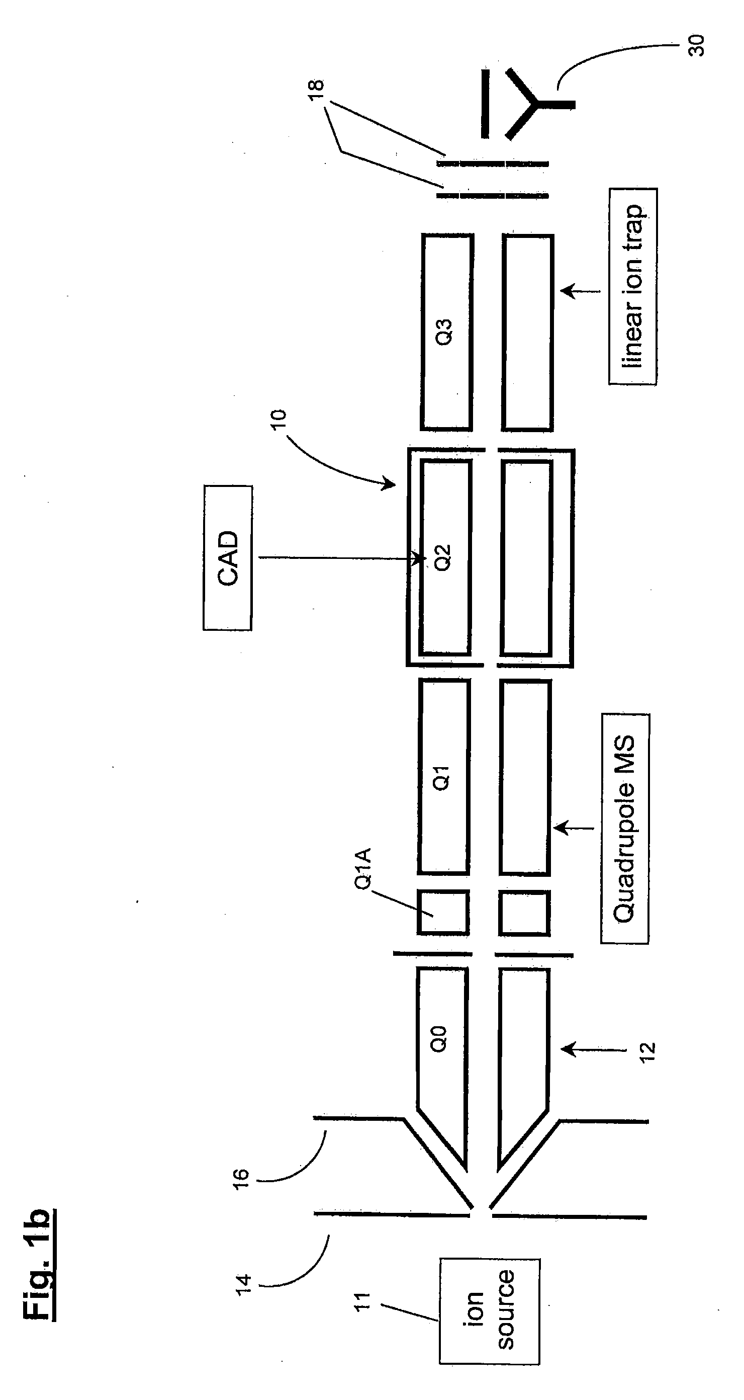
[0020]A 4000 QTRAP™ system (Applied Biosystems|MDS Sciex) was used for collection of MS data and all detection were performed in positive ion mode using Turbolonspray™. Experiments were also performed on a modified instrument allowing the introduction of a pulsed gas into the trapping region. When MS3 is performed on a QqLIT, the first stage of fragmentation (MS2) occurs via collision induced dissociation (CID) in the collision cell. The fragments generated in the collision cell were transferred for a specific amount of time to the LIT at a given energy (typically 8 eV). After a brief cooling period, the fragment of interest was isolated by applying resolving DC and the excitation step was initiated. Typically, with the transfer energy used, the excitation time varies between 70-100 ms depending on the nature of the fragment ion. When the energy used to transfer the fragment ions was increased, it was observed that there was sufficient residual internal energy in the fragment ion such that less time was required for the excitation and capture of low mass fragment ions (typically associated with more energetic fragmentation). Using this approach, the MS3 fragmentation was performed with an excitation time in the order of 20 ms. The use of a pulsed valve to increase the local pressure in various embodiments, showed benefits, for example, in the form of a further increase in fragmentation efficiency.

Problems solved by technology

The accelerated ions can collide with other molecules within the trap, resulting, for sufficiently high collision energies, in fragmentation of the ions.
However, not all RF potentials result in fragmentation of the ions.
Other oscillatory motions may not be of sufficient amplitude, and thus may impart insufficient energy to fragment the ions.
In some of these low-amplitude, low-energy cases, the ions may even lose energy during a collision.

Method used


Image

  • Method of operating a linear ion trap to provide low pressure short time high amplitude excitation with pulsed pressure
  • Method of operating a linear ion trap to provide low pressure short time high amplitude excitation with pulsed pressure
  • Method of operating a linear ion trap to provide low pressure short time high amplitude excitation with pulsed pressure

Examples


example 1

Caffeine

[0091]A comparison of the fragmentation of a caffeine ion, m / z=195, without, and with, injection of a neutral collision gas of neutral collision is shown in FIG. 11. The top spectrum (a) corresponds to the condition where no collision gas is injected during fragmentation, and it yields a 2.1% fragmentation efficiency when exciting the parent ions at 12.5 mV(0-pk) amplitude in a base pressure of 3.7×10⁻⁵ Torr. The bottom spectrum shows 13.1% fragmentation efficiency when exciting the same ion at an amplitude of 21.5 mV(0-pk) with the pulsed valve used to inject the collision gas. For each trial the excitation time was 25 ms. In this experiment the injection of the collision gas increased the fragmentation efficiency by more than a factor of six.

example 2

Lidocaine

[0092]Without injection of the collision gas, less fragmentation for short excitation times was observed. Referring to FIG. 12, the fragmentation efficiency for a Lidocaine ion, m / z=235, with (open circles) and without (filled circles) collision gas injection, is shown. For an excitation time of 10 ms the fragmentation efficiency is about 10% without injection and about 75% with injection, a gain in fragmentation efficiency by a factor of about 7.5. For an excitation time of 25 ms the gain in efficiency drops to about 2.9, and at 100 ms the gain drops even further to about 1.3. The data shows that the fragmentation efficiency, with gas injection, for this ion does not improve significantly for excitation times beyond about 25 ms, whereas the fragmentation efficiency, without gas injection, for the same ion slowly improves for excitation times up to 150 ms. However, using the present teachings the same efficiency seen at 150 ms without collision gas can be obtained in about ...

example 3

Excitation Period

[0093]A plot of the gain in ion fragmentation efficiency under conditions of collision gas injection compared to conditions without gas injection for various m / z ratios for two different excitation periods is shown in FIG. 13. The ions fragmented were those listed in Table 2. Two data sets are shown corresponding to excitation times of 25 ms (filled circles) and 100 ms (open circles). For each measurement the excitation amplitude was selected to maximize fragmentation of the parent ion. The data of FIG. 13 shows that the observed gains in fragmentation efficiency are greatest for short excitation times and low ion masses.


PUM


Abstract

Methods for fragmenting ions in an ion trap are described. These methods involve a) selecting parent ions for fragmentation; b) retaining the parent ions within the ion trap for a retention time interval, the ion trap having an operating pressure of less than about 1×10⁻⁴ Torr; c) providing a RF trapping voltage to the ion trap to provide a Mathieu stability parameter q at an excitement level during an excitement time interval within the retention time interval; d) providing a resonant excitation voltage to the ion trap during the excitement time interval to excite and fragment the parent ions; e) providing a non-steady-state pressure increase of at least 10% of the operating pressure within the ion trap by delivering a neutral gas into the ion trap for at least a portion of the retention time interval to raise the pressure in the ion trap to a varying first elevated-pressure in the range between about 6×10⁻⁵ Torr to about 5×10⁻⁴ Torr for a first elevated-pressure duration; and f within the retention time interval and after the excitement time interval, terminating the resonant excitation voltage and changing the RF trapping voltage applied to the ion trap to reduce the Mathieu stability parameter q to a hold level less than the excitement level to retain fragments of the parent ions within the ion trap. The excitation time interval and the first elevated-pressure duration substantially overlap in time.

Description

[0001]This is a non-provisional application of U.S. application No. 61 / 025,057 filed Jan. 31, 2008. The contents of U.S. application No. 61 / 025,057 are incorporated herein by reference.FIELD[0002]The invention relates generally to a method of operating a linear ion trap mass spectrometer.INTRODUCTION[0003]Ion traps are scientific instruments useful for the study and analysis of molecules. These instruments contain multiple electrodes surrounding a small region of space in which ions are confined. Oscillating electric fields and static electric fields are applied to the electrodes to create a trapping potential. Ions that move into this trapping potential become “trapped”—that is, restricted in motion to the ion-confinement region.[0004]During their retention in the trap, a collection of ionized molecules may be subjected to various operations (such as, for example without limitation, fragmentation or filtering). The ions can then be transmitted from the trap into a mass spectrometer...

Claims


Application Information

Patent Timeline
Patent Type & Authority Applications(United States)
IPC IPC(8): B01D59/44
CPCH01J49/426H01J49/0063H01J49/24H01J49/005
Inventor GUNA, MIRCEABLANC, YVES LECOLLINGS, BRUCE
Owner MDS ANALYTICAL TECH A BUSINESS UNIT OF MDS
Learn More