
Drill

Inactive Publication Date: 2009-07-30
OSG
View PDF12 Cites 4 Cited by
  • Summary
  • Abstract
  • Description
  • Claims
  • Application Information

AI Technical Summary

Benefits of technology

[0010]According to the drill as defined in claim 1, at least the surface of the cutting edge is coated with a hard compound, and the film thickness dimension of the hard compound is set to be within the range of 0.1 μm or more and 1.0 μm or less. If the film thickness dimension of the hard compound is less than 0.1 μm, the surface of the cutting edge cannot be sufficiently hardened, which makes it impossible to ensure wear resistance.
[0011]On the other hand, if the film thickness dimension of the hard compound is more than 1.0 μm, the cutting edge becomes rounded, resulting in a decrease in sharpness. As a result, the chip breaking performance decreases, causing a deterioration in machined hole accuracy and drill breakage due to chip packing. For these reasons, by setting the film thickness dimension of the hard compound to be within the range of 0.1 μm or more and 1.0 μm or less, there is an effect in that it is possible to ensure wear resistance, and prevent a deterioration in machined hole accuracy and drill breakage.
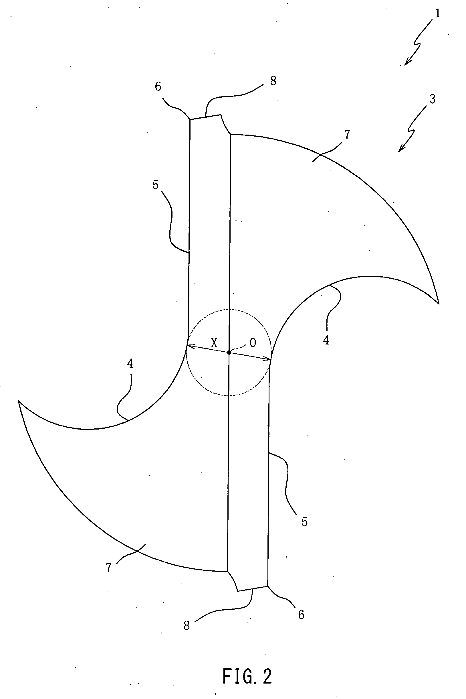
[0012]Further, the thickness dimension of the web thickness formed by the web of the groove portion is set to be within the range of 0.15 D or more and 0.25 D or less relative to the outer diameter D of the cutting edge. If the thickness dimension of the web thickness is smaller than 0.15 D, the strength of the drill decreases, making the drill prone to breakage. On the other hand, if the thickness dimension of the web thickness is larger than 0.25 D, the groove portion becomes shallow, resulting in a decrease in chip dischargeability. As a result, chip welding is induced, causing a deterioration in machined hole accuracy and drill breakage. For these reasons, by setting the thickness dimension of the web thickness to be within the range of 0.15 D or more and 0.25 D or less, there is an effect in that it is possible to endure the strength of the drill, and prevent a deterioration in machined hole accuracy and drill breakage.
[0013]Further, by setting the film thickness dimension of the hard compound and the web thickness to be within the above-mentioned ranges and using them in combination, chip dischargeability can be synergistically improved. As a result, there is an effect in that it is possible to prevent chip welding to thereby synergistically improve the life of the drill.
[0014]According to the drill as defined in claim 2, in addition to the effect provided by the drill as defined in claim 1, the average grain size of tungsten carbide forming the drill is set to be 0.5 μm or less. Therefore, there is an effect in that it is possible to ensure the hardness of the drill to thereby achieve extended life of the drill.
[0015]Further, there is an effect in that if the hardness is the same, a drill whose average grain size is set to 0.5 μm or less makes it possible to ensure toughness and prevent chipping as compared with a drill whose average grain size is set to be larger than 0.5 μm.

Problems solved by technology

However, the above-described drill does not provide a sufficient measure for facilitating the discharge of chips.
As a result, troubles as drill breakage are caused, resulting in a decrease in tool life.

Method used


Image

  • Drill
  • Drill
  • Drill

Examples


Embodiment Construction

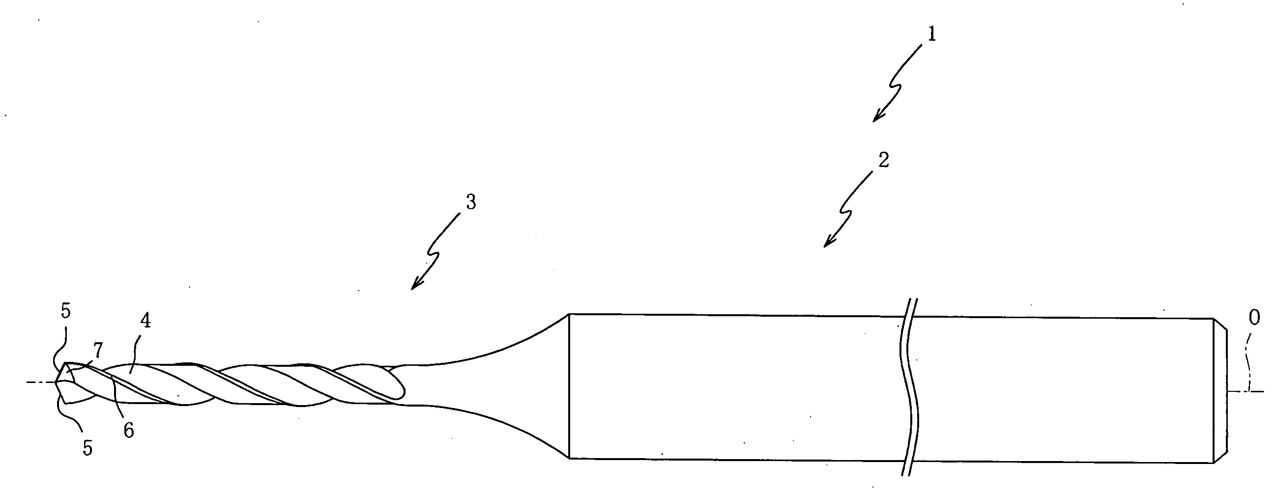
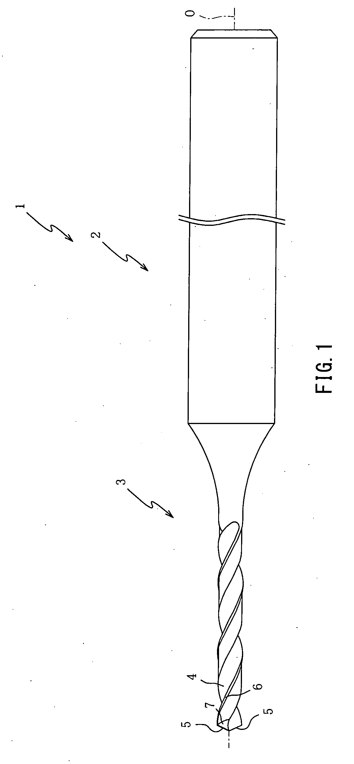
[0025]Hereinbelow, preferred embodiments of the present invention will be described with reference to the attached drawings. FIG. 1 is a front view of a drill 1 according to an embodiment of the present invention. It should be noted that illustration of the axial length of a shank 2 is omitted in FIG. 1.

[0026]The drill 1 is a cutting tool of a small diameter for drilling a hole in a stainless work material such as a shaft part, a nozzle part, or a medical part by means of torque transmitted from machining equipment (drill press or the like). As shown in FIG. 1, the drill 1 mainly includes a shank 2 held by the above-mentioned machining equipment, and a drill body 3 that performs cutting of a workpiece.

[0027]It should be noted that the surface of the drill 1 is coated with TiAIN that is a hard compound, and the film thickness dimension of TiAIN is set to be within the range of 0.1 μm or more and 1.0 μm or less. If the film thickness dimension of TiAIN is less than 0.1 μm. the surface...


PUM

PropertyMeasurementUnit
Thicknessaaaaaaaaaa
Thicknessaaaaaaaaaa
Angleaaaaaaaaaa

Abstract

A drill is designed to ensure wear resistance to achieve extended tool life. In the drill, at least the surface of the cutting edge is coated with a hard compound, and the film thickness dimension of the hard compound is set to be within the range of 0.1 μm or more and 1.0 μm or less. Further, the thickness dimension of the web thickness formed by the web of the groove portion is set to be within the range of 0.15 D or more and 0.25 D or less relative to the outer diameter D of the cutting edge. Consequently, chip dischargeability can be synergistically improved. As a result, there is an effect in that it is possible to prevent chip welding to thereby synergistically improve the life of the drill.

Description

TECHNICAL FIELD[0001]The present invention relates to drills, and more specifically to a drill that can ensure wear resistance and achieve extended tool life.BACKGROUND ART[0002]A drill is a drilling tool for cutting a workpiece by a cutting edge formed at the tip. The surface of a drill is generally coated with a hard compound such as TiN, TiAIN, or TiCN. Such a coating hardens the surface of the drill for improved wear resistance, thereby achieving extended tool life.[0003]However, when the surface of a drill is coated, its cutting edge becomes rounded, resulting in a decrease in the sharpness of the drill. Such a decrease in sharpness leads to a decrease in chip braking performance, causing chip packing, which brings about troubles such as a deterioration in machined hole accuracy and drill breakage.[0004]In view of this, Japanese Patent Application Laid-Open Publication No. 2003-251503 describes a technique in which the film thickness dimension of a coating is set to be within t...

Claims


Application Information

Patent Timeline
IPC IPC(8): B23B51/02
CPCB23B51/02B23B2224/24B23B2228/10Y10T408/9097B23B2251/241B23B2251/443C23C30/005B23B2228/105
Inventor MASUDA, NORIHIRO
Owner OSG
Learn More