Tube fouling monitor

a technology of fouling monitor and tube, which is applied in the field of heat exchangers, can solve the problems interfering with heat transfer coefficient, and achieve the effects of reducing heat flow, minimizing sensor variations, and accurate average measurement of fouling signals

Inactive Publication Date: 2009-07-30
INTEK
View PDF26 Cites 19 Cited by
  • Summary
  • Abstract
  • Description
  • Claims
  • Application Information

AI Technical Summary

Benefits of technology

[0012]The instrument sensor consists of a tube, which is plugged into the expanded normal outlet end of selected tube(s) in the outlet water box. Singular or multiple heaters and temperature sensor pairs are located around an outside diameter of the flow tube and sealed in a larger diameter thermally insulated jacket. In one configuration pairs of temperature sensors with one only containing an electrical power heater are used to measure a temperature differential between the two temperature sensor sites which can be used to quantify over time a heat transfer coefficient measurement change that varies with the amount of fouling or change in flow rate. Assuming the circulating water mass flow rate remains constant, the change in ΔT over time becomes a measurement of fouling change. Other pairs may be located at regions containing an antifouling coating to be used as a reference to compare with the fouling sensor pair for quantifying fouling and for water mass flow rate measurement, Mcw. Also the reference temperature sensors provide a measure of condenser tube outlet circulating water temperature with the instrument located normally on the outlet end of a condenser tube. This temperature allows determination of the amount of heat absorbed by the water when making use of available inlet circulating water temperature to obtain ΔTcw and from the mass flow rate, using equation 1 (see below). The primary purpose of using multiple sites for locating temperature sensor—temperature sensor / heater pairs around a diameter in the sensor is to obtain an accurate average measurement of fouling signal because of the preferential nature of fouling by precipitation, which accumulates on the bottom of horizontal tubes, minimizing sensor variations from circumferential local fluid velocity differences and possible longitudinal temperature differences in the direction of flow.
[0013]Another purpose of the fouling meter is to measure the effects of air in suspected air bound zones of the tube bundle. The existence and description of cause for and the means to remove air bound zones have been identified in U.S. Pat. Nos. 6,526,755 and 7,065,970 by Harpster and continued in pending applications. Air or noncondensable gas on the steam side of condenser tubes have a similar effect on the tube heat transfer coefficient as the fouling on the cooling water side; it interferes with the heat transfer coefficient reducing heat flow. Locating the fouling meter in these air bound regions provides direct thermal impedance measurements of the air bound region, particularly when internal tube fouling is absent. These measurements can be compared to sensors in regions known not to be in air bound regions to determine a measure of fouling on the inside of tubes.
[0014]In some applications it may become advantageous to install the disclosed sensor at the normal inlet and of the tube particularly if fouling is sensitive to the temperature rise of the circulating water. Here, the sensor remains relatively clean showing little effect of fouling providing more direct measure of flow rate and inlet circulating water temperature when coupled with an independent measurement of tube outlet temperature which may be obtained with a simple thermocouple sensor, tube fouling is determined in an identical manner as above, using equations (1) through (5).

Problems solved by technology

Air or noncondensable gas on the steam side of condenser tubes have a similar effect on the tube heat transfer coefficient as the fouling on the cooling water side; it interferes with the heat transfer coefficient reducing heat flow.

Method used


Image

  • Tube fouling monitor
  • Tube fouling monitor
  • Tube fouling monitor

Examples


Embodiment Construction

A. Purpose

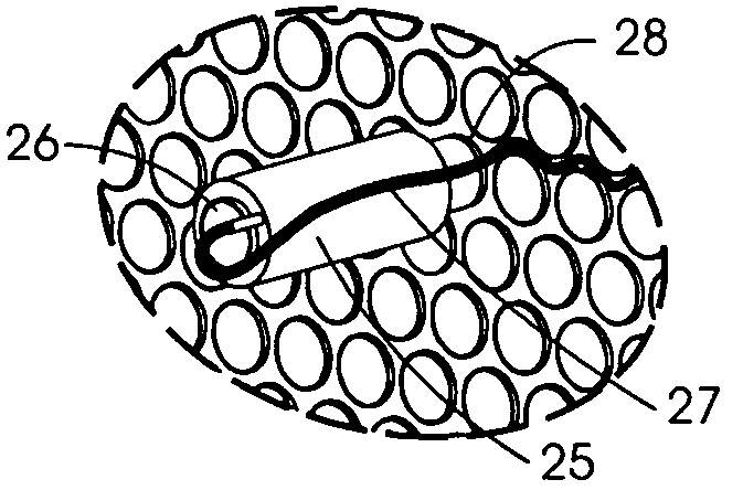
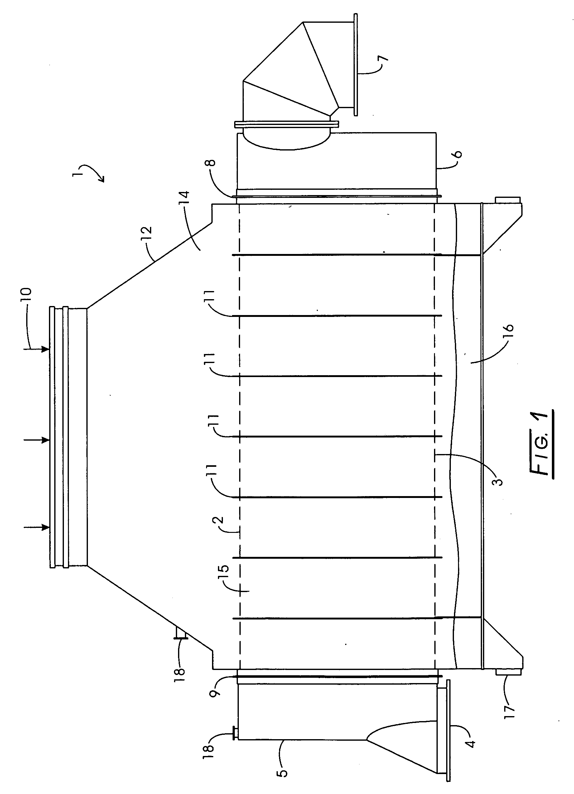
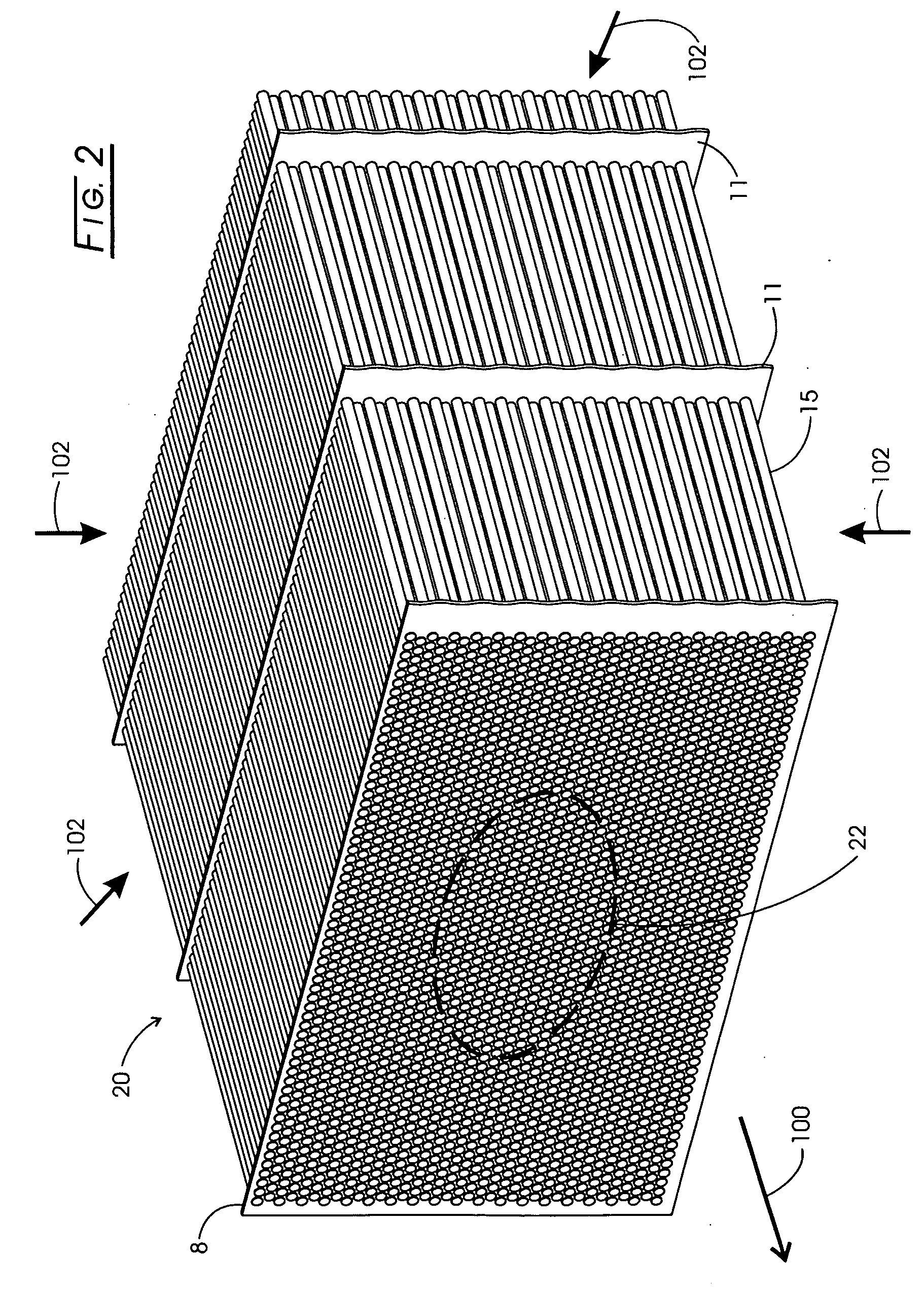
[0041]The disclosed Tube Fouling Monitor (TFM) is a unique device used to monitor fluid properties such as flow rate and exit temperature in several selected tubes to calculate tube fouling on the inner and outer wall of the monitored tube as well as monitor in situ the effect of fouling on the clean heat transfer coefficient of the TFM. The ability to monitor this fouling is valuable in maintaining some heat exchanger systems for optimized performance, to identify the cause of high dissolved and deleterious gases in condensate and the need to perform retrofit modifications of the heat exchanger configuration.

[0042]For optimized condenser performance, tubes should be as clean as possible and the condenser should operate at below its original design pressure with measured dissolved oxygen below 5 ppb, show relatively uniform outlet circulating water temperature rise from all tubes in the tube bundle and be maintained with air in-leakage below the design capacity of the exha...


PUM


Abstract

A method for measuring the effects of fouling of heat transfer tubes in heat exchangers where a cooling fluid at lower temperature is removing heat from another fluid at higher temperature includes placing a nonrestrictive mass flow rate and temperature measuring tube extension sensor on a tube outlet end; obtaining the tube inlet temperature for deriving the rise in fluid temperature; analytically computing the amount of heat transferred from the hot fluid to the cold fluid; from tube length, inside and outside tube diameter, analytically deriving the tube heat transfer coefficient; and determining tube fouling factor, the value of which is the fraction of the clean tube heat transfer coefficient available for transferring heat, by dividing the heat transfer coefficient by the known heat transfer coefficient of an unfouled tube.

Description

CROSS-REFERENCE TO RELATED APPLICATIONS[0001]This application claims benefit of provisional application Ser. No. 61 / 062,780 filed on Jan. 28, 2008, the disclosure of which is expressly incorporated herein by reference.STATEMENT REGARDING FEDERALLY SPONSORED RESEARCH[0002]Not applicable.BACKGROUND[0003]The present disclosure generally relates to heat exchangers and more particularly, to power plant condensers for determining, by measurement, the extent of internal or external fouling of selected heat exchanger tubes that represent the condition of other nearby tubes in the area. ASME PTC 12.2 methods, related to condensers, suggest individual tube measurements that are expensive and suffer from assumptions of measured steam temperature. The EPRI TR-107397 methods relate to the general field of heat exchangers does address the need to understand flow conditions in individual tubes. Further, the ASME method is costly and the single tube flow equipment is not suitable for long-term use ...

Claims


Application Information

Patent Timeline
Patent Type & Authority Applications(United States)
IPC IPC(8): B60H1/00
CPCG01K17/06F28B1/02F28F2200/00F28D7/1653F28F19/00F28B11/00
Inventor HARPSTER, JOSEPH W.HARPSTER, TIMOTHY J.
Owner INTEK
Why Eureka
Try Eureka