
Dynamic rate adjustment to splice compressed video streams

Inactive Publication Date: 2009-07-16
VVNET
View PDF62 Cites 39 Cited by
  • Summary
  • Abstract
  • Description
  • Claims
  • Application Information

AI Technical Summary

Benefits of technology

[0036]The techniques described herein may enable one or more of the following advantages. An advantage of the rate adjustment technique is its ease of implementation which enables scalability. In addition, it is highly flexible in terms of the required burst rate, and the duration and timing of the burst. Another advantage is the quality of the video around the splice point is not compromised, and the solution is agnostic of the specific compression layer. Additionally, the solution may be applied to seamlessly splice streams whose compression layer bits are encrypted, without requiring decryption of those bits or any knowledge of the specific encryption scheme. The techniques described herein are particularly well suited for deployment in telco networks and “video over DOCSIS” in cable MSO networks, where the communications channel for video provides a variable bandwidth capacity, allowing for the burst from the splicer.

Problems solved by technology

The DCT is an extremely compute intensive step, as it involves matrix multiplication operations.
Note that if bits are lost either due to a VBV overflow or a violation of channel capacity, it may result in a long lasting glitch if the affected frame or frames are referenced by other prediction-based frames.
Moreover, any underflow represents lost time, which may be critical in the case of live video streams.
Commercial splicers typically support several concurrent splicing operations, but do not scale very well.
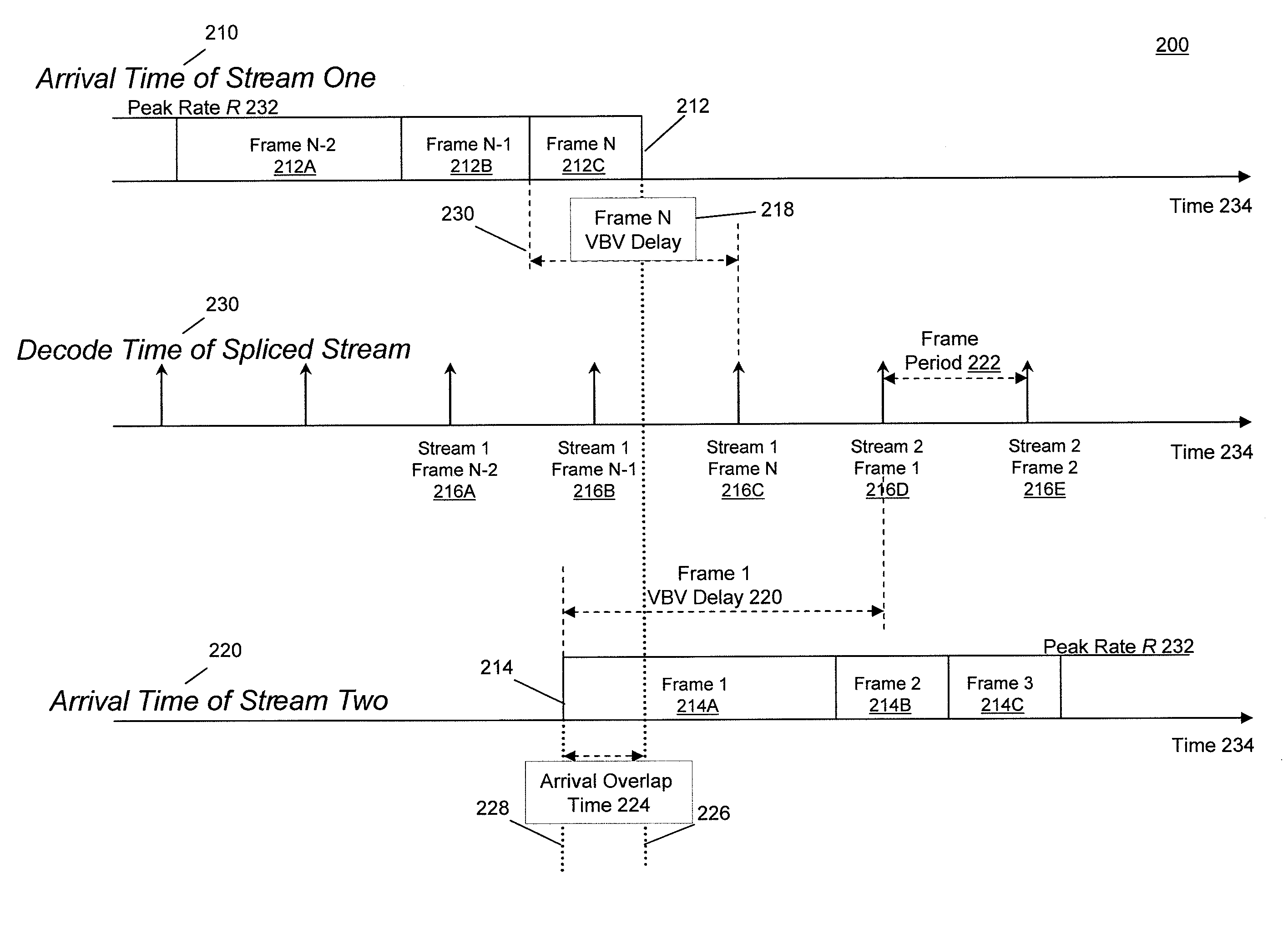
One of the most difficult problems associated with splicing compressed video streams is related to the variable frame rate of arrival at the receiver and the corresponding VBV buffer management.
This may cause an arrival overlap time 224 of some of the trailing bits of the first stream and the initial bits of the second stream, resulting in a violation of the bit-rate of the channel and an overflow of the receiver buffer.
However, this may cause an underflow in the VBV buffer and a freeze-frame artifact, thereby rendering the splice non-seamless.
This solution is extremely compute intensive, as it involves full decode and encode operations, and does not scale very well.
Moreover, transrating compromises video quality around the splice point.
This approach found limited favor in the industry due to the difficulty in pre-conditioning streams so as to allow for the worst-case overlap scenario.

Method used


Image

  • Dynamic rate adjustment to splice compressed video streams
  • Dynamic rate adjustment to splice compressed video streams
  • Dynamic rate adjustment to splice compressed video streams

Examples


Embodiment Construction

[0047]In general overview, a splicer receives a first compressed video stream of bits and buffers the first video stream of bits in a first buffer. The splicer receives a second compressed video stream of bits to splice into the first compressed video stream. The splicer buffers the second compressed video stream of bits in a second buffer. The splicer determines a departure time for a splice in-point of the second compressed video stream of bits. The splicer adjusts a rate of the first compressed video stream of bits, a rate of the second compressed video stream of bits, or both to achieve the departure time. Adjusting the rate of the first compressed video stream of bits, the rate of the second compressed video stream of bits, or both that ensures the last bit of the out-point frame from the first stream departs before the first bit of the in-point frame from the second stream.

[0048]FIG. 3 shows the splicing system 300 for seamlessly splicing multiple video streams. The splicing s...


PUM


Abstract

Described are computer-based methods and apparatuses, including computer program products, for dynamic rate adjustment to splice video streams. A splicer receives a first compressed video stream of bits and buffers the first video stream of bits in a first buffer. The splicer receives a second compressed video stream of bits to splice into the first compressed video stream. The splicer buffers the second compressed video stream of bits in a second buffer. The splicer determines a departure time for a splice in-point of the second compressed video stream of bits. The splicer adjusts a rate of the first compressed video stream of bits, a rate of the second compressed video stream of bits, or both to achieve the departure time.

Description

FIELD OF THE INVENTION[0001]The description relates generally to computer-based methods and apparatuses, including computer program products, for dynamic rate adjustment to splice compressed video streams.BACKGROUND[0002]Digital compressed video based on the Moving Picture Experts Group (MPEG) standards has become the predominant choice for delivering and storing video content. The International Organization for Standardization (ISO) / International Electrotechincal Commission (IEC) 13818 suite specifies the widely deployed MPEG-2 standard, while ISO / IEC 14496 specifies the increasingly popular MPEG-4 standard which provides for a much improved coding efficiency and enhanced error robustness. In general, MPEG distinguishes between the compression layer, responsible for coding the raw video and associated audio signals, and the systems layer, responsible for the carriage, synchronization and timing of multiple such compressed signals. It is also common to find MPEG-4 compressed signals...

Claims


Application Information

Patent Timeline
IPC IPC(8): H04N7/12H04B1/66H04N11/02
CPCH04N21/23406H04N21/23424H04N21/44016H04N21/242H04N21/44004H04N21/23805
Inventor HLUCHYJ, MICHAEL G.KRISHNAN, SANTOSHLAWLER, CHRISTOPHERZHU, QIN-FAN
Owner VVNET
Learn More