
Submersible High Illumination LED Light Source

a high-lighting, led light source technology, applied in the field of submersible light sources, can solve the problems of increasing the risk of bodily injury or death of workers, workers in other underwater environments, and the use of ac may also increase the risk of ac use, so as to achieve greater life expectancy, increase the duration between required lamp maintenance, and save materials and labor.

Inactive Publication Date: 2009-07-16
LIGHTS CAMERA ACTION
View PDF17 Cites 105 Cited by
  • Summary
  • Abstract
  • Description
  • Claims
  • Application Information

AI Technical Summary

Benefits of technology

[0016]All of the foregoing and other implementations of a submersible high illumination light source assembly may comprise or exhibit one or more of the following advantages. Implementations may provide illumination both in-air and underwater (and may be moved between in-air and underwater environments while operating), without requiring that a submersible light assembly unit is first powered down before being submerged, and / or removed from, an underwater environment. The duration between required lamp maintenance may be increased as the high-illumination LED lamps utilized in particular implementations may possess greater life-expectancy than other types of lamps. Cost savings in materials and labor may be realized due to the decreased maintenance required. Disposal costs of waste may decrease as fewer used lamps are generated at less frequent intervals. Accidents, pollution, and cleanup and replacement costs may be reduced as glass and mercury may be eliminated from lamp designs. Disposal cost savings may be particularly acute where used lamps must be designated and disposed of as “radioactive waste,” such as, by way of non-limiting example, when such lamps have been exposed to gamma radiation in nuclear environments.

Problems solved by technology

Due to the inherently hazardous nature of underwater work in nuclear reactor cavities and spent fuel pools, along with the sensitive nature of the materials to be handled, extensive illumination is typically required for the safety of workers and others.
Workers in other underwater environments, such as in oceanographic or other underwater work, also typically have considerable underwater lighting requirements.
While this arrangement may allow both incandescent bulbs and HPS bulbs to be used in conventional electrical configurations, the use of AC may also increase the risk of bodily injury or death to workers, as compared to other electrical current configurations such as Direct Current (DC).
Also, in the case nuclear reactor cavities and spent fuel pools, lamp replacement may typically require the labor of two workers due to safety requirements.
During a lamp change in a nuclear reactor cavity or spent fuel pool, workers may be undesirably exposed to radiation.
Additionally, due to labor, material and other expenses, the cost of replacing a conventional underwater incandescent bulb in nuclear reactor cavities and spent fuel pools may approach or exceed several hundred dollars.
While incandescent bulbs are typically inexpensive to purchase initially, they nevertheless convert electricity into light energy inefficiently compared to other light sources such as, by way of non-limiting example, High Pressure Sodium (HPS) and may thus be comparatively expensive to operate.
Like conventional incandescent bulbs, replacement of HPS bulbs may also typically require the labor of two workers, due to safety requirements.
During a lamp change, whether incandescent or HPS, workers may be exposed to radiation.
Additionally, due to labor, material and other expenses, the cost of replacing a conventional underwater HPS bulb in nuclear reactor cavities and spent fuel pools may approach or exceed a thousand dollars.
A mercury spill can be merely inconvenient in the case of oceanographic or other non-nuclear underwater work, or may be catastrophic when occurring in a nuclear reactor cavity or spent fuel pool.
Moreover, while HPS bulbs convert electricity into light energy more efficiently than incandescent bulbs, they may still be expensive to operate.
When incandescent lamps and / or HPS lamps are used in nuclear reactor cavities and spent fuel pools, they may be exposed to gamma radiation and high temperatures.
Typically, when incandescent and / or HPS bulbs used in nuclear reactor cavities and spent fuel pools require replacement, the discarded bulbs may be required to be disposed of as “radioactive waste,” at significant expense, due to their prior contact with gamma radiation.

Method used


Image

  • Submersible High Illumination LED Light Source
  • Submersible High Illumination LED Light Source
  • Submersible High Illumination LED Light Source

Examples


examples

[0076]Implementations may be designed to operate at a variety of voltages and wattages and may produce a variety of lumen total outputs, thereby operating with a variety of efficacies. In lighting design, “efficacy” refers to the amount of light (luminous flux) produced by a lamp (a light bulb or other light source), usually measured in lumens, as a ratio of the amount of energy consumed to produce it, usually measured in watts. This is not to be confused with “efficiency” which is always a dimensionless ratio of output divided by input which for lighting relates to the watts of visible energy as a ratio of the energy consumed in watts.

[0077]Accordingly, for the exemplary purposes of this disclosure, some submersible high illumination light source assembly implementations may operate at about 40 volts, between about 5 amperes to about 12 amperes, and from about 200 watts to about 500 watts, while other submersible high illumination light source assembly implementations may operate a...


PUM


Abstract

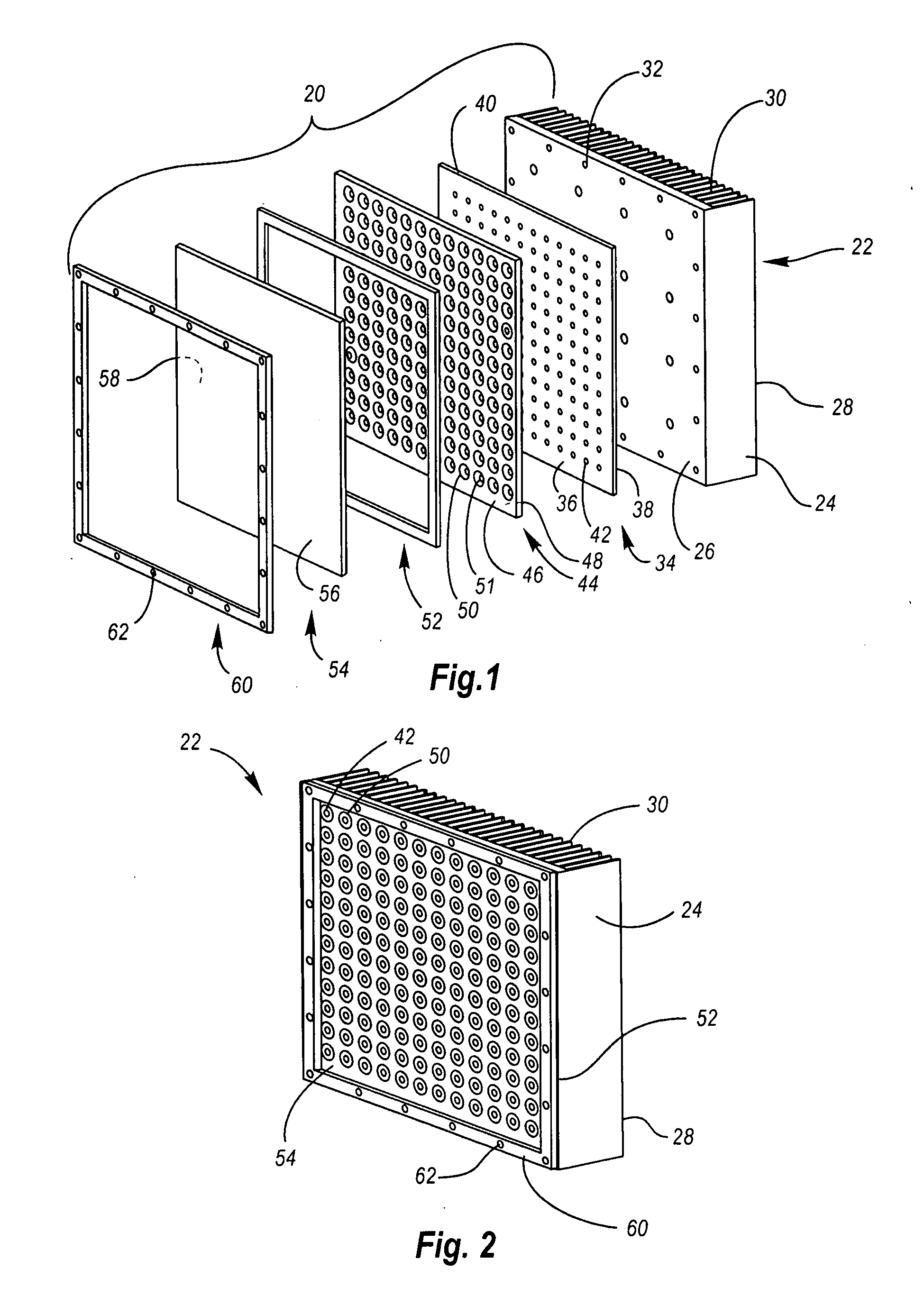
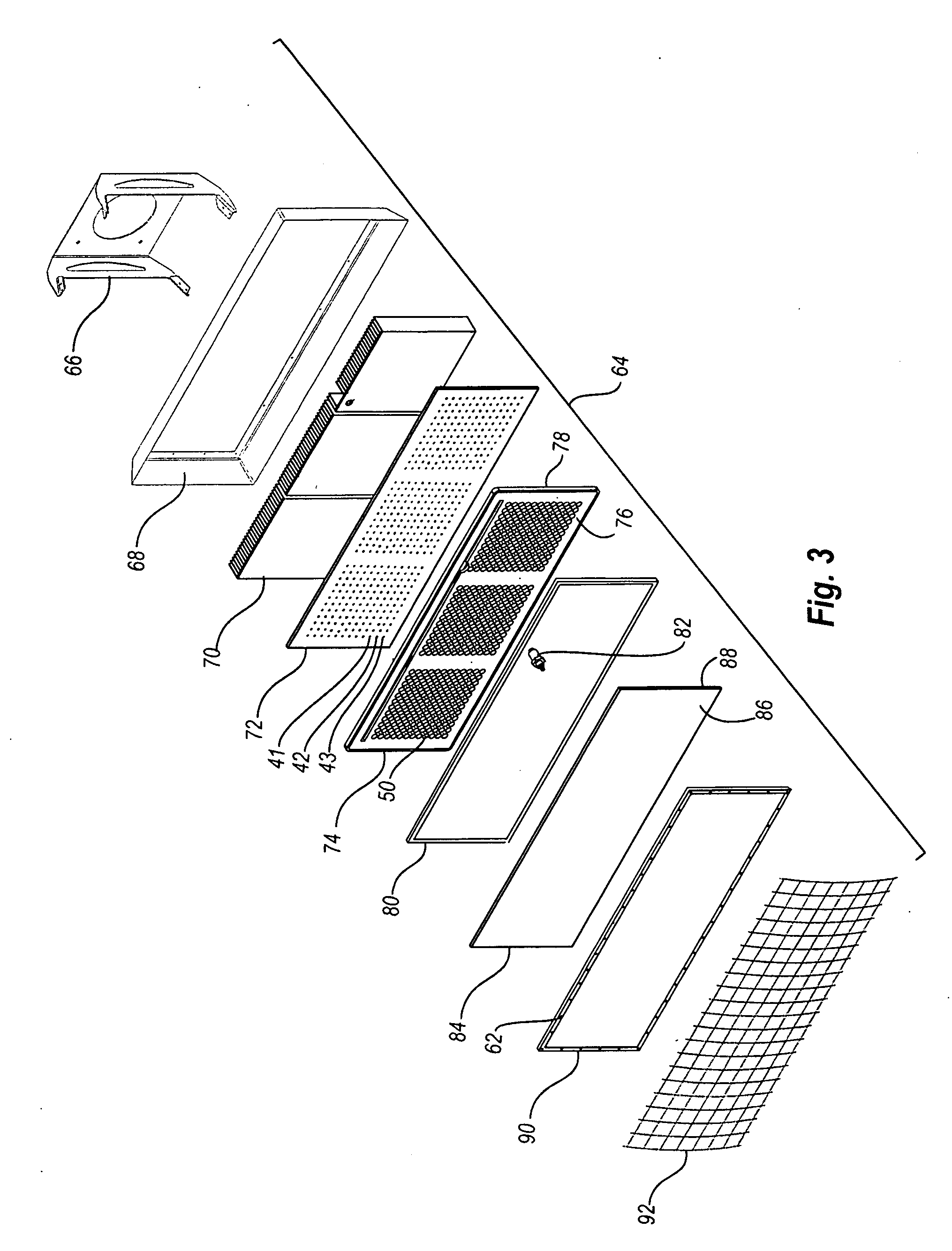
A submersible high illumination light source assembly is disclosed, comprising at least one module. A module comprises a heat sink having a front surface and a rear surface. A printed circuit board comprising one or more electrical connections sized and shaped to couple with a plurality of high-illumination light emitting diode (LED) lamps is in thermal communication with the front surface of the heat sink. The plurality of high-illumination LED lamps are coupled in electronic communication with the printed circuit board via the one or more electrical connections. At least one reflector is sized and shaped to accept the insertion of one or more of the plurality of high-illumination LED lamps. A window is in watertight communication with the reflector plate. The submersible high illumination light source assembly operates both when submerged underwater and exposed to air.

Description

CROSS REFERENCE TO RELATED APPLICATIONS[0001]This document claims the benefit of the filing date of U.S. Provisional Patent Application 61 / 021,433, entitled “Submersible High Power LED Light Source” to Ahland, et al. which was filed on Jan. 16, 2008, the disclosure of which is hereby incorporated entirely herein by reference.BACKGROUND[0002]1. Technical Field[0003]Aspects of this document relate generally to submersible light sources.[0004]2. Background Art[0005]Many examples of underwater work environments exist, requiring adequate lighting for workers to efficiently and successfully perform their designated functions. One example of an underwater work environment exists within the context of nuclear power plants. Nuclear power plants conventionally include nuclear reactor cavities and spent fuel pools. Such nuclear reactor cavities and spent fuel pools, in operation, typically contain water or other liquid solutions. It is often required of workers performing maintenance, repair a...

Claims


Application Information

Patent Timeline
IPC IPC(8): F21V29/00
CPCF21S2/005F21V7/0083F21V15/02F21V25/10F21V29/004F21V31/005F21V29/89F21Y2101/02F21Y2105/001F21V3/00F21V17/12F21V29/763F21W2131/40F21Y2105/10F21Y2115/10
Inventor AHLAND, III, WALTER W.LA BELLE, CHRISKULAGA, THOMASKREMER, MICHAEL
Owner LIGHTS CAMERA ACTION
Learn More