
Patient transfer device

a technology for transferring devices and patients, applied in the field of patient transfer devices, can solve the problems of inability to move a person who is bedridden, inconvenient to carry, and high effort required by a care-giver to physically move a person, and achieve the effect of low friction coefficien

Inactive Publication Date: 2009-07-16
JEWELL WILLIAM +2
View PDF28 Cites 16 Cited by
  • Summary
  • Abstract
  • Description
  • Claims
  • Application Information

AI Technical Summary

Benefits of technology

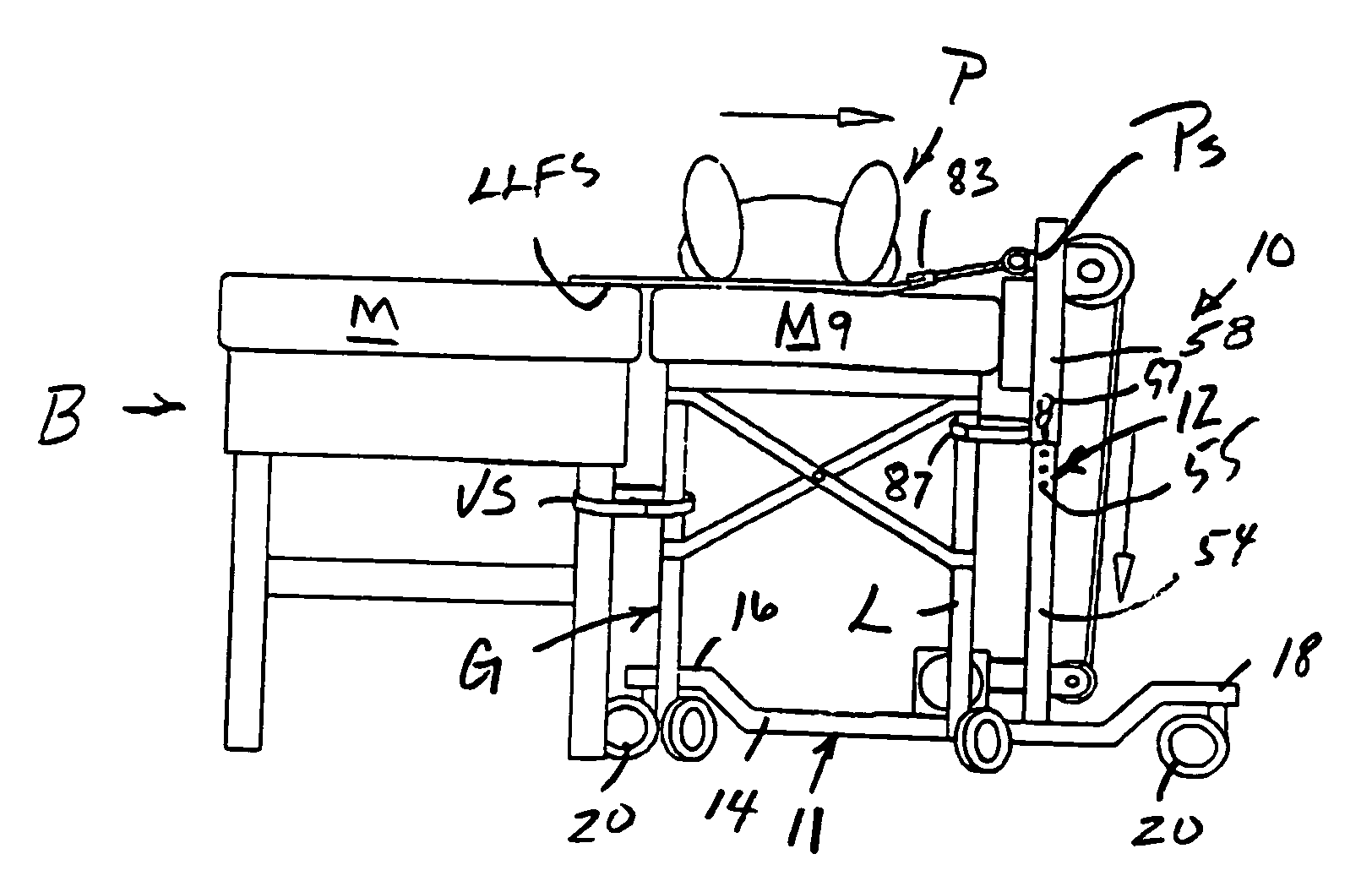
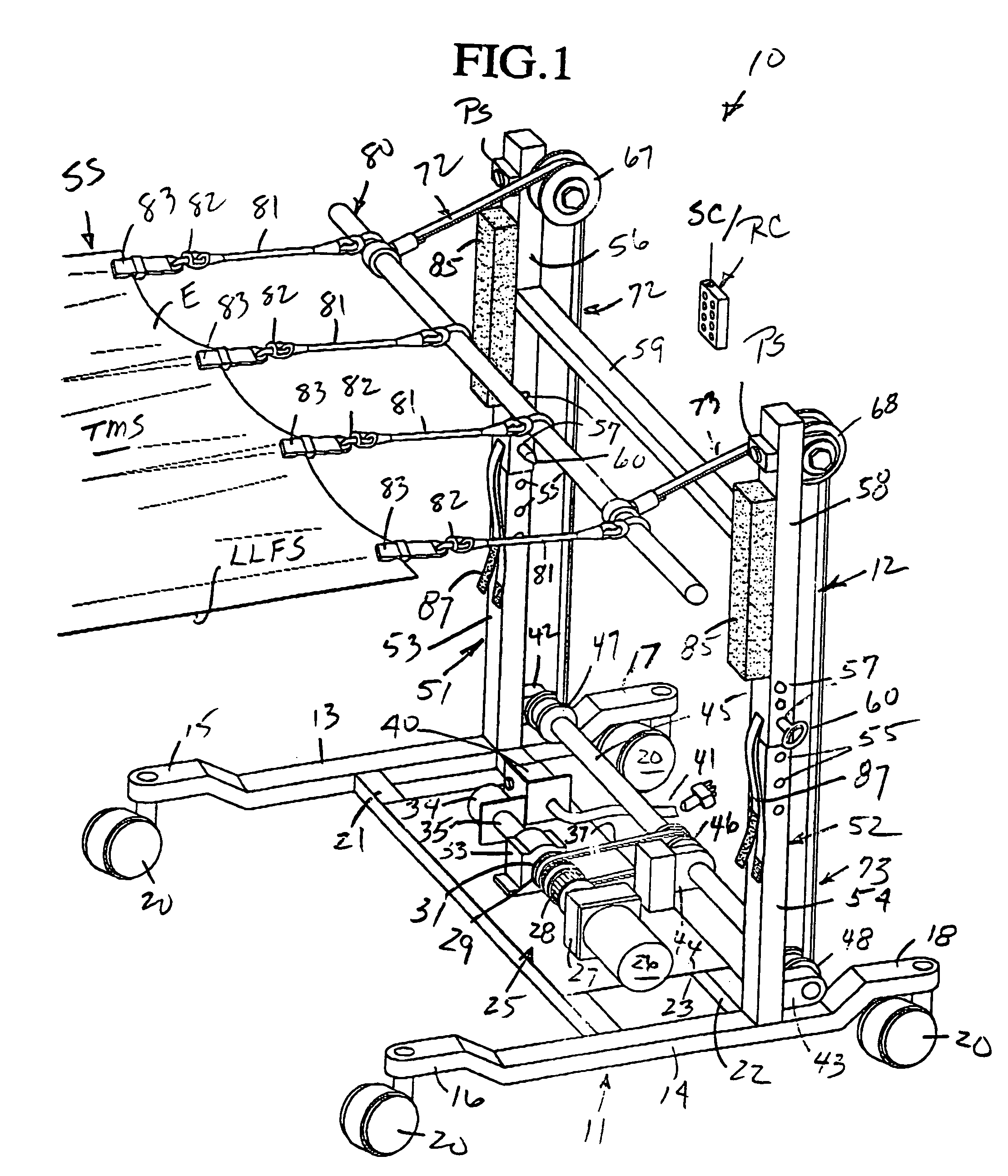
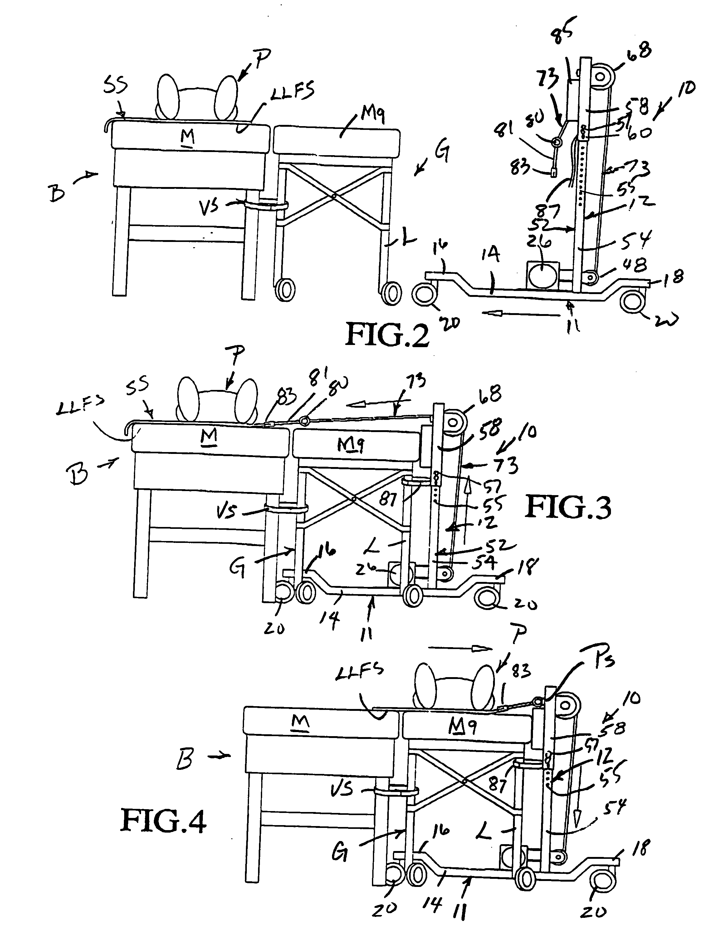
[0003]In accordance with the present invention, a transfer device for moving a bed-ridden patient to and from a bed and / or a gurney or the like includes a self-sustained mobile unit defined by a platform or base mounted on wheels or castors which carries an upstanding structure, preferably in the form of a pair of vertical supports, each having an upper and a lower end carrying respective idler and drive pulleys. Flexible cables are entrained about the pulleys and upper ends of the cables are connected to a pull bar which is in turn connected by attachment clips to a slide sheet which can be a conventional bed sheet but preferably is a sheet of material having an extremely low coefficient of friction at least upon a lower surface thereof which slides upon / across a bed or gurney mattress, a gurney upper support surface, or the like. A lower end of each of the cables is connected to a driven shaft which is in turn driven by a reversible drive motor and a reduction gearing to impart sufficient power to pull the slide sheet and the patient thereupon readily easily from a bed to a gurney or vice versa absent any physical effort on the part of the care-giver / attendant.
[0004]The vertical supports are located toward an end of the base or platform remote from a forward end thereof which is located a considerable distance beneath a gurney, for example, onto which a patient is to be moved from an adjacent bed. The vertical supports include pads which bear against the gurney, and as the patient is being slid from the bed to the gurney, any turning moment which might otherwise tend to tilt or cock the transfer device is resisted by the location of the forward end of the platform well beneath the gurney and the contact between the gurney and the vertical supports. This assures that the driving force of the electric motor operating through the reduction gearing and imparted to the slide sheet is efficiently utilized as a pulling force, as opposed to a moment-creating force. Moment-creating forces are also reduced by constructing the vertical supports so as to be vertically adjustable to generate pulling forces applied to the slide sheet which are substantially horizontal and preferably slightly upwardly inclined to the horizontal to maximize the pulling forces applied to the slide sheet and minimize the creation of turning moment forces.
[0005]Conventional clamping mechanisms may be associated with the vertical supports for clamping the same to the bed / gurney, etc. to assure efficient patient transfer operations, as might be required if a patient is relatively heavy (200-300 pounds).
[0006]A control system for operating the reversing motor preferably includes a hand-held remote control unit provided with appropriate on / off and directional switches and a switch to control a solenoid for engaging a clutch to impart desired directional rotation to the lower driven pulleys which are in turn connected to a single lower driven shaft. Override / safety proximity switches are also utilized to preclude unintended transfer motion of the slide sheet to thereby prevent patient / caretaker injury.

Problems solved by technology

The effort required by a care-giver to physically move a bed-ridden person is substantial and many times results in injury, particularly lower back injury, to the care-giver.
Absent effective mechanical assistance, as is presently the case, a care-giver must necessarily physically lift, slide and / or carry the bed-ridden person from his / her bed to and from a gurney, a wheelchair, a toilet chair, a shower chair or some other type of bathroom function device which is highly strenuous.
Equally strenuous, particularly with relatively heavy patients, is the seemingly simple task of moving a patient horizontally between two supporting surfaces at substantially identical levels, such as an adjacent bed and gurney.
An immobile person lacking physical strength is dead weight and, whether pushed or pulled, many care-givers / attendants barely have enough strength to move such a person.
Equally dangerous is the application of physical pushing and / or pulling forces to the bed-ridden person which can, in and of itself, cause physical pain and / or damage, particularly when the bed-ridden person is old, may have brittle bones, etc.
Mechanical transfer devices for transferring bed-ridden persons are available to care-givers but, for the most part, these require considerable strength to manually operate the transfer device.
Each conveyor is relatively complex and necessitates being welded to the gurney and / or to the bed frame or being otherwise fastened thereto.
An obvious disadvantage of this patient transfer device is the necessity of either securing a conveyor to every bed or to every gurney, which is extremely expensive and obviously still involves physical strength to rotate the handle and pull the patient to or from the bed / gurney.
The latter patents recognize the seriousness of the problem presented to the healthcare industry, but the patient transfer device of the latter patents is at best an extremely inadequate effort aimed toward a solution of the problem at a high cost per patient transfer device.

Method used


Image

  • Patient transfer device
  • Patient transfer device
  • Patient transfer device

Examples


Embodiment Construction

[0012]A novel patient transfer device constructed in accordance with this invention is illustrated in FIG. 1 of the drawings and is generally designated by the reference numeral 10.

[0013]The patient transfer device 10 is adapted to transfer an individual, patient, bed-ridden person P (FIGS. 2 through 4) or the like from a conventional bed B to a gurney G or vice versa in a manner to be described more fully hereinafter.

[0014]The patient transfer device 10 includes a mobile unit defined by platform or a base 11 and an upstanding vertical structure 12.

[0015]The base 11 is substantially elongated and includes a pair of substantially parallel high strength steel longitudinal tubes 13, 14 having upwardly offset forward ends or end portions 15, 16 and similar upwardly offset rear ends or end portions 17, 18, respectively. Lockable / unlockable castors or wheels 20 of a conventional construction are conventionally attached to the forward end portions 15, 16 and the rear end portions 17, 18 of...


PUM


Abstract

A transfer device transfers an individual from a bed to an adjacent support surface or vice versa and includes a mobile unit defined by a base and an upstanding structure having lower and upper end portions respectively adjacent to and remote from the base. A lower drive pulley and an upper idler pulley are located respectively adjacent to and remote from the base. A motor rotates the lower drive pulleys to wind thereupon a cable at least partially entrained upon the upper idler pulley. Clamps releasably connect the cable to a slide interposed between an individual and a bed or an adjacent support surface upon which an individual is reposed whereby upon operation of the motor, the slide with an individual thereon is pulled from a bed to an associated adjacent support surface or vice versa.

Description

BACKGROUND OF THE INVENTION[0001]The present invention relates to solving ongoing and persistent problems encountered by care-givers when transferring a bed-ridden person from his / her bed to and from another support, such as a gurney, a bath / toilet-type platform, etc., or vice versa. The effort required by a care-giver to physically move a bed-ridden person is substantial and many times results in injury, particularly lower back injury, to the care-giver. Elderly, weak and / or essentially immobile persons who are being treated in hospitals or reside in high maintenance nursing homes are continually transferred between a bed and a gurney or a bed and a wheelchair for a multitude of purposes, such as treatment in operating theaters, therapy rooms, x-ray rooms, etc. Absent effective mechanical assistance, as is presently the case, a care-giver must necessarily physically lift, slide and / or carry the bed-ridden person from his / her bed to and from a gurney, a wheelchair, a toilet chair, a...

Claims


Application Information

Patent Timeline
Patent Type & Authority Applications(United States)
IPC IPC(8): A61G7/10
CPCA61G7/1026A61G2200/32A61G7/1046
Inventor JEWELL, WILLIAMGODETTE, ROBERT G.RAMIK, VINCENT L.
Owner JEWELL WILLIAM
Learn More