
Apparatus and method for controlling continuously variable transmission and program for performing the control method

Active Publication Date: 2009-07-09
TOYOTA JIDOSHA KK
View PDF6 Cites 12 Cited by
  • Summary
  • Abstract
  • Description
  • Claims
  • Application Information

AI Technical Summary

Benefits of technology

[0012]According to the second aspect, it is determined whether the deceleration of the vehicle is less than or equal to a predetermined reference deceleration. When the deceleration of the vehicle is less than or equal to the predetermined reference deceleration, the increase in the clamping pressure applied to the transmission belt is prohibited. Thus, during a quick braking operation, in which the deceleration of the vehicle is higher than the predetermined reference deceleration, the clamping pressure applied to the transmission belt may be increased. However, during a smooth and gradual braking operation, in which the deceleration of the vehicle is less than or equal to the predetermined reference deceleration, increases in the clamping pressure applied to the transmission belt are prohibited. Thus, when excessive torque is applied to the transmission belt, the slippage of the transmission belt on the pulleys may be reduced by increasing the clamping pressure applied to the transmission belt. However, when excessive torque is not applied to the transmission belt, an increase in the clamping pressure applied to the belt is avoided and a shock is reduced.
[0014]According to the third aspect, it is determined whether the elapsed time since operation of the brake is greater than or equal to the predetermined reference time. When it is determined that the elapsed time since the operation of the brake is greater than or equal to the predetermined reference time if the vehicle speed falls to or below the predetermined reference speed when the brake is being operated, an increase in the clamping pressure of the transmission belt is prohibited. Thus, when it is determined that the time elapsed since the operation of the brake is less than the predetermined reference time and it is thus recognized that the vehicle is undergoing a quick braking operation, the clamping pressure applied to the transmission belt may be increased. Meanwhile, when it is determined that the time elapsed since the operation of the brake is greater than or equal to the predetermined reference time and it is thus recognized that the vehicle is undergoing a smooth and gradual braking operation, an increase in the clamping pressure applied to the transmission belt is prohibited. Thus, when excessive torque is applied to the transmission belt, the slippage of the transmission belt on the pulleys can be reduced by increasing the clamping pressure applied to the transmission belt. However, when excessive torque is not applied to the transmission belt, an increase in the clamping pressure applied to the transmission belt is avoided and a transmission shock is reduced.

Problems solved by technology

However, during a quick braking operation of a vehicle, the output speed of the CVT is quickly reduced, so that torque applied to the transmission belt is excessively increased.
Meanwhile, when the speed of the vehicle is high, excessive torque is not applied to the transmission belt.
However, when the braking operation is started while the vehicle is driven at a high speed, the clamping pressure of the transmission belt is increased stepwisely at the time that the speed of the vehicle has been reduced to a predetermined low speed, so that the clamping pressure of the transmission belt may deviate from the brake operation timing, and may cause a transmission shock.

Method used


Image

  • Apparatus and method for controlling continuously variable transmission and program for performing the control method
  • Apparatus and method for controlling continuously variable transmission and program for performing the control method
  • Apparatus and method for controlling continuously variable transmission and program for performing the control method

Examples


first embodiment

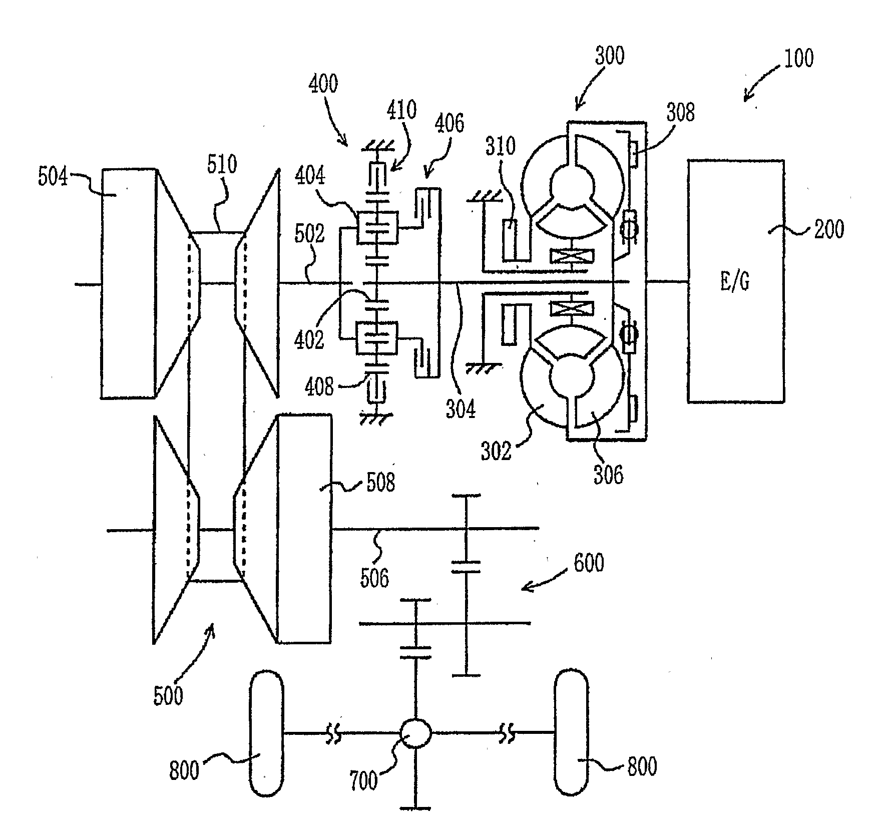
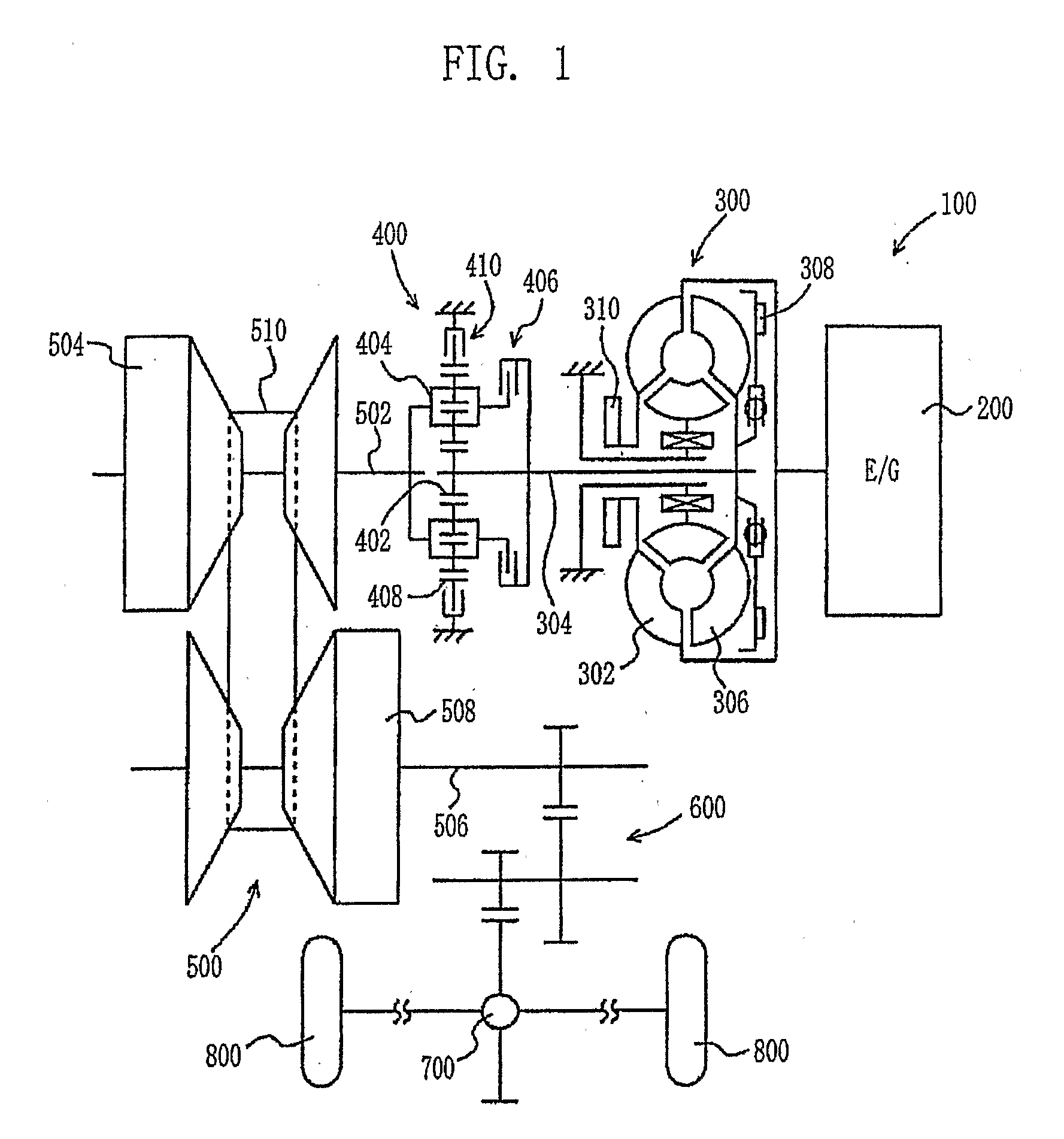
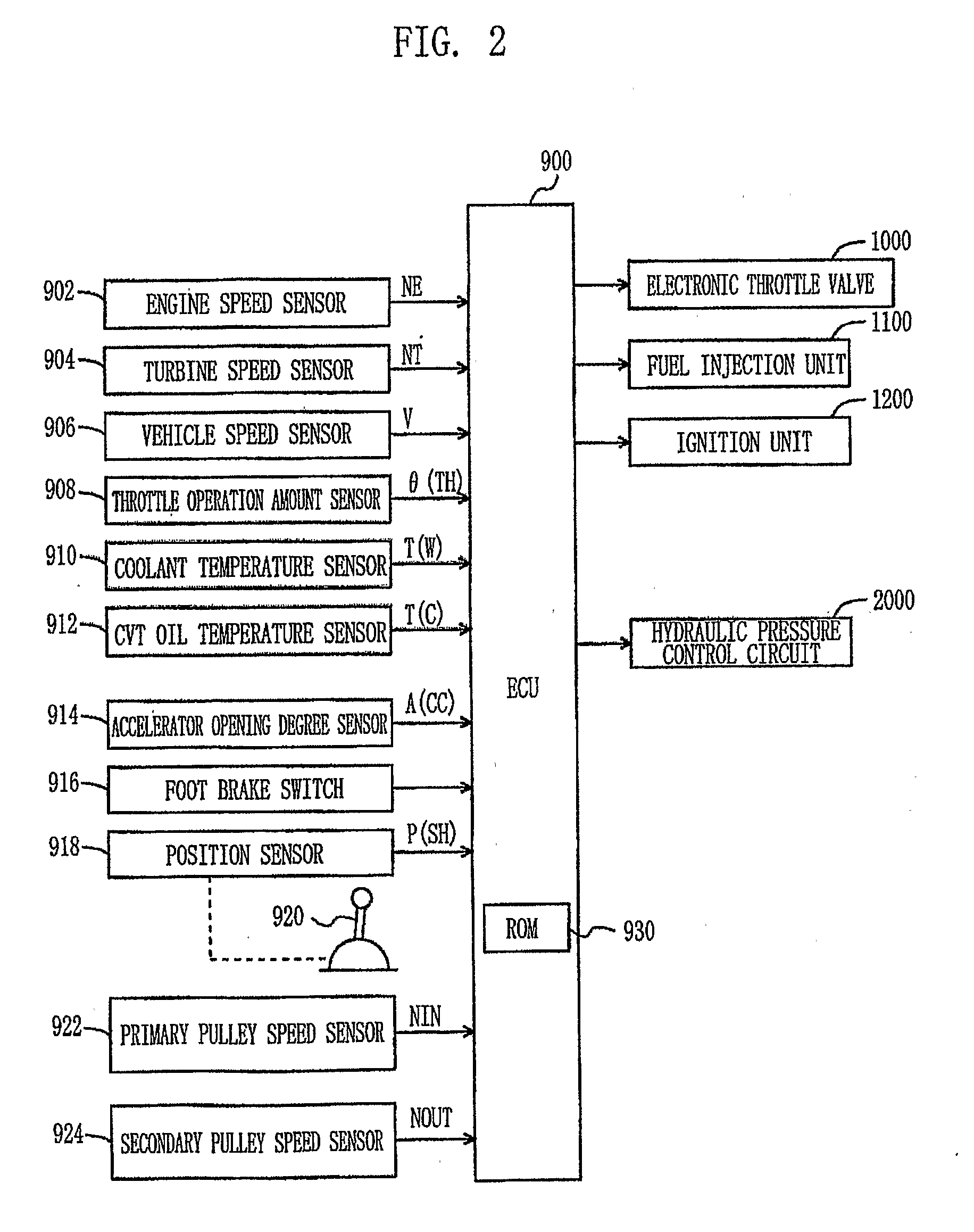
[0035]A vehicle, equipped with a control apparatus according to the present invention, will be described below with reference to FIG. 1. The output power of an engine 200, which is included in a drive unit 100 installed in the vehicle, is transmitted to a belt-type CVT 500 both through a torque converter 300 and a forward / reverse drive switching unit 400. The output power of the belt-type CVT 500 is transmitted both to a reduction gear 600 and to a differential gear unit 700, and is distributed to the left and right drive wheels 800. The drive unit 100 is controlled by an Electronic Control Unit (ECU) 900, which will be described in detail later herein. In the embodiment, the control apparatus for the CVT is operated under the control of the ECU 900, which executes a program stored in a Read Only Memory (ROM) 930 of the ECU 900.

[0036]The torque converter 300 comprises a pump blade 302, which is connected to the crankshaft of the engine 200, and a turbine blade 306, which is connecte...

second embodiment

[0115]In the second embodiment, when the brake operation determining unit 940 determines that the brake is being operated and the vehicle speed determining unit 942 determines that the vehicle speed is less than or equal to a threshold speed V(0), the clamping-pressure increasing unit 954 controls the SLS linear solenoid valve 2210 to increase the clamping pressure of the belt stepwisely to a pressure P(ON) that is higher than a normal pressure P(OFF), which is set when the brake is not being operated.

[0116]When the vehicle speed falls the threshold speed V(0) when the brake operation determining unit 940 determines that the brake is being operated, the clamping-pressure stepwise increasing unit 956 controls the SLS linear solenoid valve 2210 to gradually increase the clamping pressure of the belt at a predetermined gradient to the pressure level P(ON) that is higher than the normal pressure P(OFF). In other words, in comparison with the clamping-pressure increasing unit 954, the cl...

third embodiment

[0124]In the third embodiment, the clamping-pressure increase-amount setting unit 958 sets the amount of increase of the clamping pressure of the belt, which is increased by the clamping-pressure increasing unit 960, according to the speed of the vehicle. When the vehicle speed is higher than the threshold speed V(0), the increase-amount is set to zero (i.e. the clamping pressure of the belt is not increased. However, when the vehicle speed is less than or equal to the threshold speed V(0), the increase-amount is set to a higher value in inverse proportion to the vehicle speed.

[0125]When the brake operating determining unit940 determines that the brake is being operated and the vehicle speed determining unit 942 determines that the vehicle speed is less than or equal to the threshold speed V(0), the clamping-pressure increasing unit 960 according to the third embodiment controls the SLS linear solenoid valve 2210 to increase the clamping pressure of the belt by the increase-amount s...


PUM


Abstract

An apparatus and method for controlling a CVT (continuously variable transmission), and a program for executing the control method that reduces a transmission shock during a braking operation. When a foot brake switch is turned on and a vehicle speed is less than or equal to a threshold speed, the ECU increases a clamping pressure applied to a transmission belt to a pressure level higher than a normal pressure. When the vehicle speed falls to or below the threshold speed when the foot brake switch is turned on, the ECU prohibits an increase in the clamping pressure applied to the transmission belt.

Description

BACKGROUND OF THE INVENTION[0001]1. Field of the Invention[0002]The present invention relates, in general, to an apparatus and method for controlling a continuously variable transmission (CVT) and a program for performing the control method. In particular, the invention relates to a technology for controlling the clamping pressure of the transmission belt of the CVT.[0003]2. Description of the Related Art[0004]In the related art, a continuously variable transmission (CVT), in which a transmission belt clamps a pair of pulleys having a variable groove width, is known. In the CVT, clamping pressure of the transmission belt prevents slippage of the transmission belt on the pulleys. However, during a quick braking operation of a vehicle, the output speed of the CVT is quickly reduced, so that torque applied to the transmission belt is excessively increased. In the above state, the transmission belt may slip on the pulleys due to the excessively increased torque, To prevent the slippage ...

Claims


Application Information

Patent Timeline
IPC IPC(8): F16H61/662G06F17/00G06F19/00F16H9/00F16H59/44F16H59/48F16H59/54F16H61/02F16H61/66
CPCF16H61/66272F16H2061/66281
Inventor INOUE, DAISUKE
Owner TOYOTA JIDOSHA KK
Learn More