
Lawn and garden battery clamp

a battery clamp and garden technology, applied in the field of battery cable clamps, can solve the problems of substantial decrease in clamping pressure, and achieve the effects of reducing clamping pressure, easy removal, and increasing clamping pressur

Inactive Publication Date: 2007-03-13
SPC INT
View PDF6 Cites 2 Cited by
  • Summary
  • Abstract
  • Description
  • Claims
  • Application Information

AI Technical Summary

Benefits of technology

The clamp provides a secure, corrosion-resistant, and tool-free connection that maintains electrical conductivity even under vibration, simplifying maintenance and reducing corrosion-related issues.

Problems solved by technology

When it is desired to remove the battery cable clamp, the handle can be pivoted in the opposite direction and a substantial decrease in the clamping pressure results.

Method used


Image

  • Lawn and garden battery clamp
  • Lawn and garden battery clamp
  • Lawn and garden battery clamp

Examples


Embodiment Construction

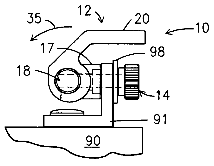
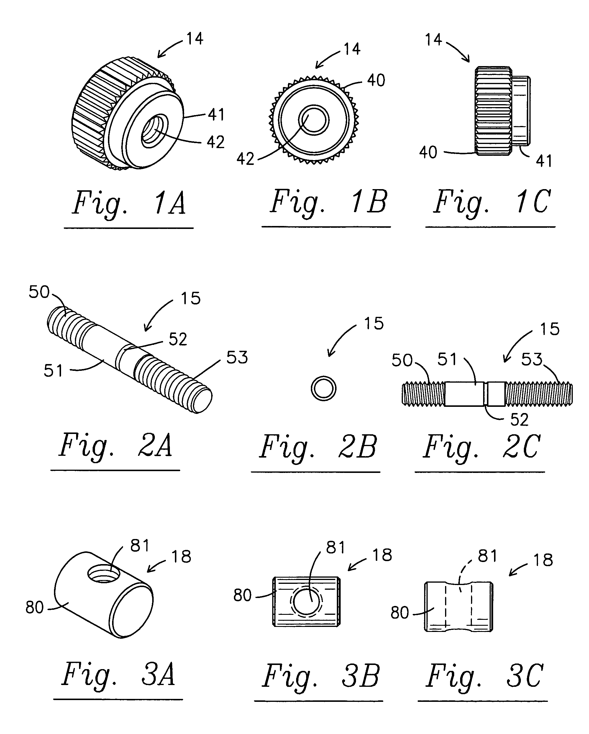
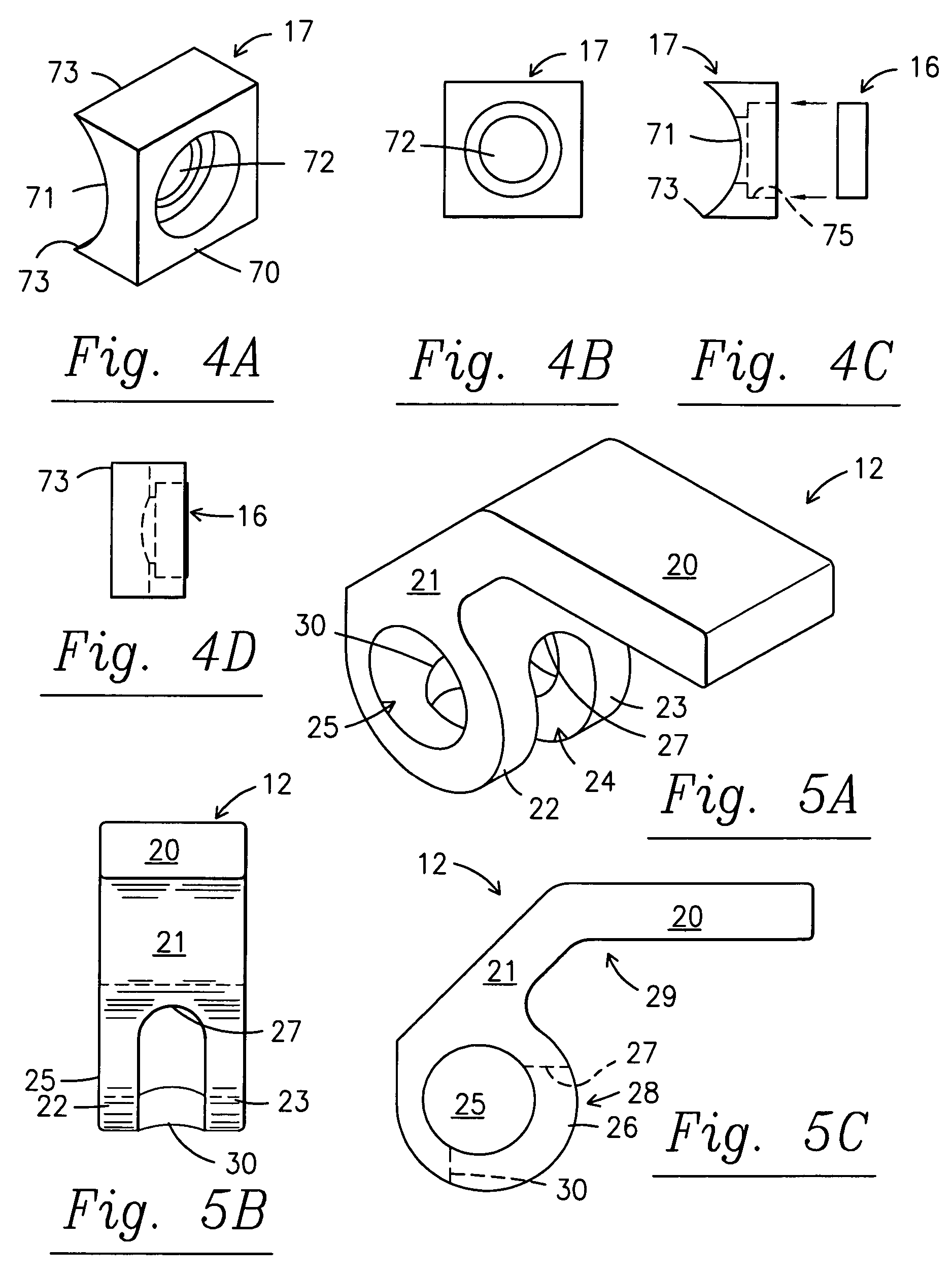
[0027]A description of the preferred embodiment of the present invention will be best understood by referring to FIGS. 1–8 of the accompany drawings. Referring first to FIG. 7, a representative prior art connection is shown. Lawn and garden battery terminal post 91 has base and upstanding rectangular panel 92 with aperture 93. Lawn and garden type battery cables 19 typically have flat rounded plate-like in the form of flat metal plate end connectors 98 with aperture 99. Apertures 93, 99 of battery terminal post 91 and cable connector 98 respectively, are aligned and the shaft 96 of bolt 94 is passed through those apertures 93, 99. Nut 92 is fastened on the threaded shaft 96 and the bolt head 95 and tightened so that nut 92 compress battery cable connector 98 against rectangular plate 92 of battery terminal post 91 to establish an electrical connection.

[0028]FIG. 6 shows an embodiment of a battery clamp 10 according to the present invention which is used to replace the nut 92 and bol...


PUM


Abstract

An improved battery cable clamp provides for toolless attachment of battery cable connectors to lawn and garden-type battery terminal posts utilizing a bossed handle, cam seat and thumbnut, preferably made of non-corrosive materials.

Description

FIELD OF THE INVENTION[0001]The present invention relates generally to battery cable clamps and more particularly a clamp designed to connect a battery cable to a lawn and garden type battery post.BACKGROUND OF THE INVENTION[0002]Many items of lawn and garden power equipment are now started or operated with battery power. For instance, many lawn tractors intended for both commercial and home use are started by battery power from lawn and garden style batteries. Other work and recreational equipment such as all terrain vehicles and jet skis also use this style battery. The standard lawn and garden battery has upstanding flat metal terminal posts with apertures to receive a bolt. The usual lawn and garden battery cable ends with a flat round metal connector with an aperture that may also be received over a bolt. Thus, the bolt is passed through openings in both the metal terminal post and the round cable connector. The nut is then threaded on the bolt and presses the flat round connec...

Claims


Application Information

Patent Timeline
Patent Type & Authority Patents(United States)
IPC IPC(8): H01R4/50
CPCH01R11/289H01R11/286
Inventor ORANGE, CHARLES M.ELLER, STEVE
Owner SPC INT
Learn More