
Radiation-curable optical glass fiber coating compositions, coated optical glass fibers, and optical glass fibers, and optical glass fiber assemblies

a technology of coating composition and coating glass fiber, which is applied in the direction of fibre mechanical structure, etc., can solve the problems of compromising the strength of connection, affecting the signal transmission capability of coated optical glass fiber, and affecting the splicing operation of optical glass fiber ribbon mass fusion, so as to improve the capability of ribbon stripping

Inactive Publication Date: 2009-07-02
DSM IP ASSETS BV
View PDF41 Cites 4 Cited by
  • Summary
  • Abstract
  • Description
  • Claims
  • Application Information

AI Technical Summary

Benefits of technology

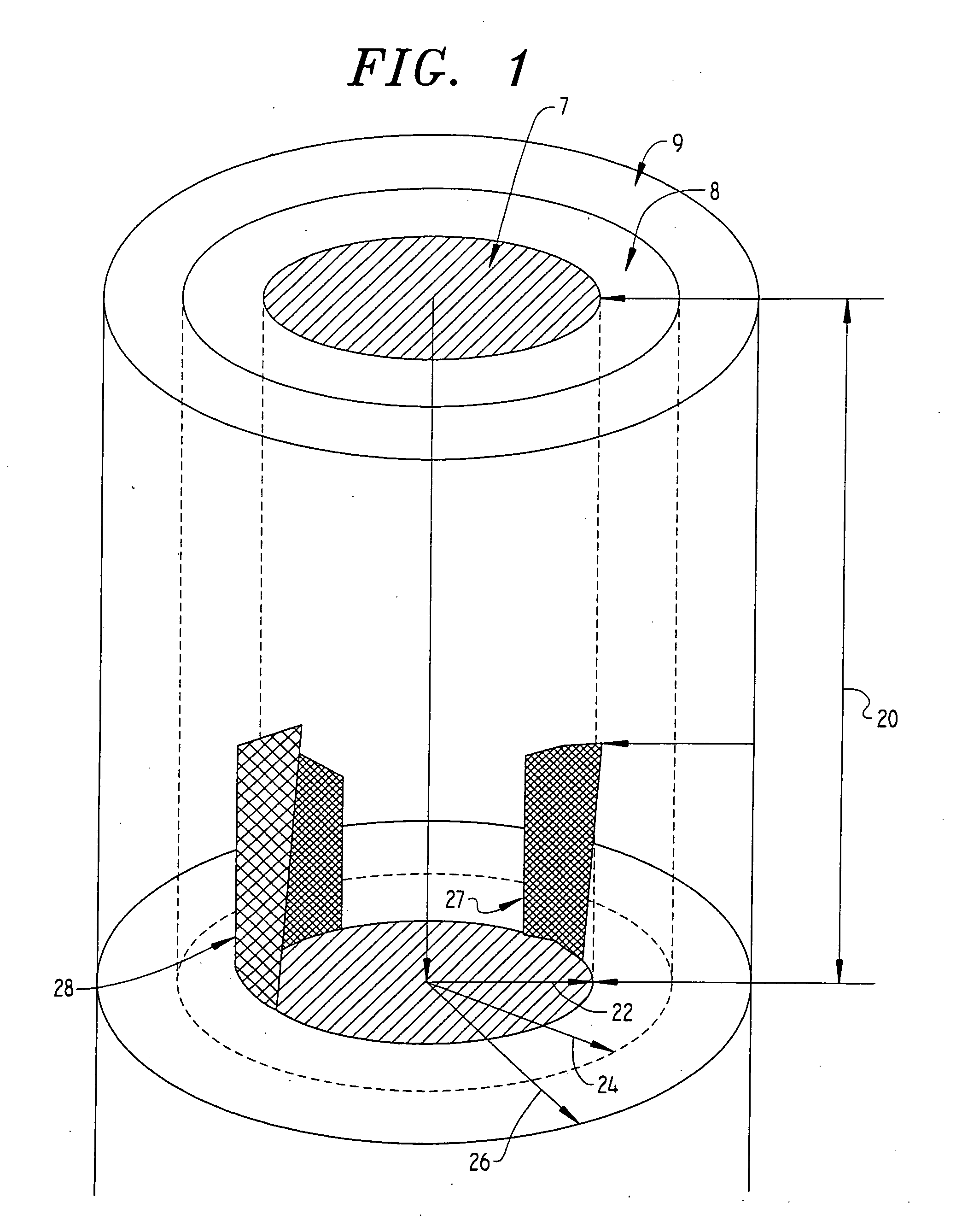
[0024]It is an objective of the present invention to provide a novel ribbon assembly having improved ribbon stripping capabilities. It is another objective of the present invention to provide a novel ribbon assembly which after ribbon stripping provides bare optical glass fibers which are substantially free of residue, that must be removed prior to forming connections to the respective selected bare optical fibers.
[0028](i) sufficient adhesion to said optical glass fiber to prevent delamination during handling and in the presence of moisture; and
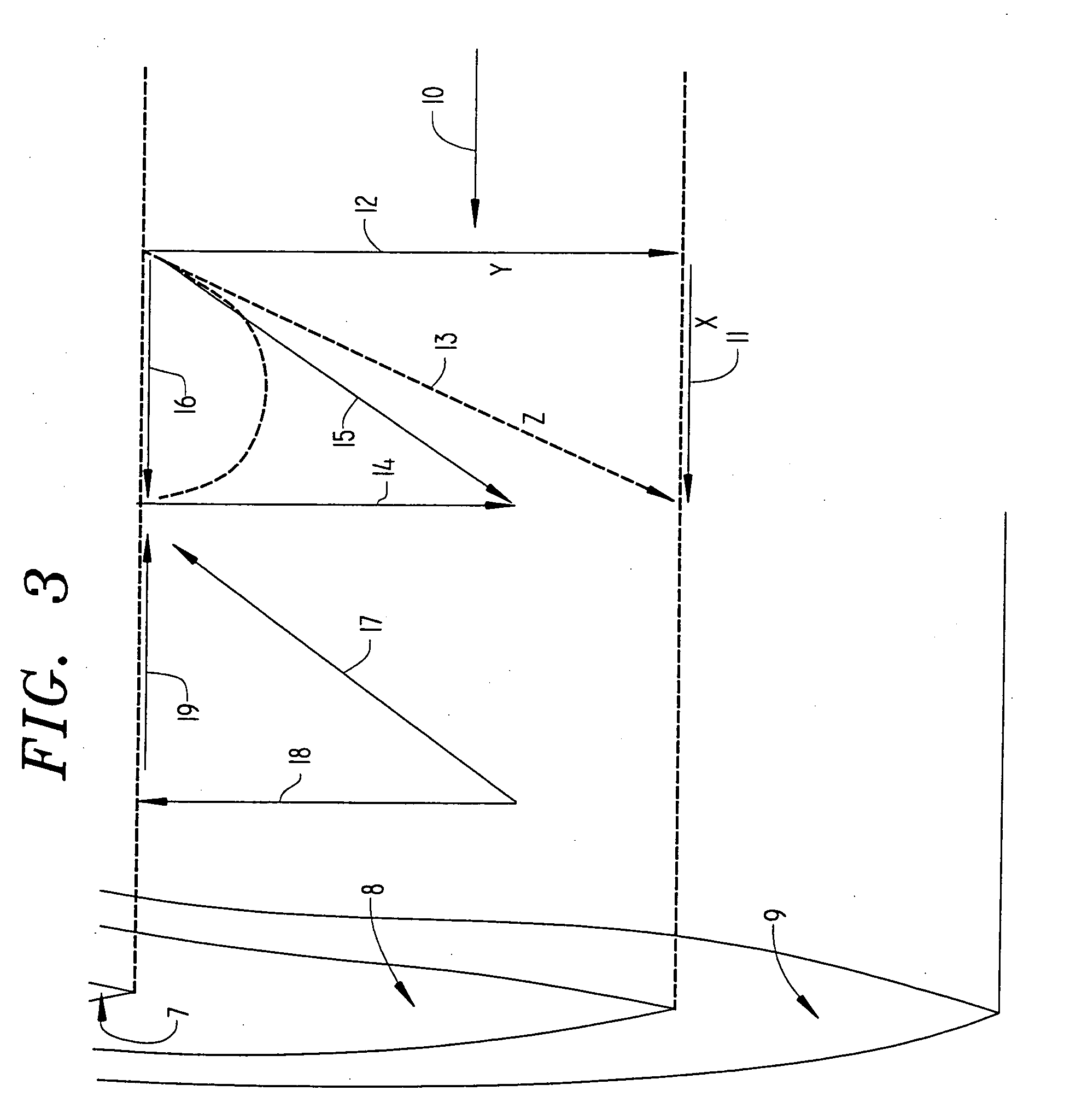
[0051]The present invention further provides a radiation-curable, inner primary optical glass fiber coating composition formulated from a composition comprising at least one radiation-curable oligomer having at least one polymeric block and at least one functional group capable of polymerization in the presence of actinic radiation connected to said at least one polymeric block. The polymeric block has a molecular weight so selected to provide said inner primary coating with a fiber friction force level between said optical glass fiber and said inner primary coating in combination with a crack propagation level that provides the inner primary coating with the functional capability of sliding off the optical glass fiber and leaving substantially no residue on the surface of said optical glass fiber during ribbon stripping when a stripping force which is less than the cohesive strength of said inner primary coating is applied to said inner primary coating.

Problems solved by technology

Microbending can lead to attenuation of the signal transmission capability of the coated optical glass fiber and is therefore undesirable.
This residue can interfere with the optical glass fiber ribbon mass fusion splicing operation, and therefore usually must be removed by wiping prior to splicing.
However, the step of removing the residue can cause abrasion sites on the bare optical glass fiber, thus compromising the strength of the connection.
While this patent discloses, at column 5, lines 10-13, that the adhesion between the inner primary coating and the optical glass fiber should be sufficient to prevent delamination of the inner primary coating from the optical glass fiber, any reduction in the adhesion between the inner primary coating and the optical glass fiber increases the possibility of such undesirable delamination, especially in the presence of moisture.
Delamination of the inner primary coating from the optical glass fiber can lead to degraded strength of the optical glass fiber as well as signal transmission attenuation disadvantages.
However, this patent fails to teach how to solve the problems associated with the residues remaining on the bare optical glass fibers after ribbon stripping conventional ribbon assemblies.
Thus, the ribbon assembly disclosed in this publication does not have the capability of removing the primary coatings on the optical glass fibers simultaneously with removal of the matrix material during ribbon stripping, so as to provide residue-free bare optical glass fibers.
Furthermore, the lubricating interfacial layer will inhibit simultaneous removal of the first protective coating with the matrix material.
Thus, this publication does not teach how to make a ribbon assembly having the capability of removing the primary coatings on the optical glass fibers simultaneously with the matrix material during ribbon stripping, so as to provide residue-free bare optical glass fibers.
However, this patent does not address the problems associated with removing the primary coating layers simultaneously with the matrix material.
Because such a coating is easily peelable, as by rubbing with finger pressure, the coating has insufficient adhesion to the surface of the optical glass fibers to prevent delamination during most uses.
Furthermore, this patent does not address the problems of ribbon stripping, but rather only the stripping of a single optical glass fiber.
However, this patent does not address the problems associated with ribbon stripping.
However, this document fails to teach a system to adjust the level of fiber friction between the adjacent surfaces of the optical glass fiber and the inner primary coating to a level which provides a resistive force that is less than the cohesive strength of the inner primary coating.
Thus, while this document teaches that the inner primary coating can be stripped more easily by incorporating liquid lubricant compounds, the inner primary coating will still leave unwanted residue on the surface of the optical glass fiber if the above described fiber friction forces are at a level which provide a resistive force that is greater than the cohesive strength of the inner primary coating.
The ability of a ribbon assembly to ribbon strip cleanly so as to provide bare optical glass fibers that are substantially free of residue is still unpredictable and the factors affecting ribbon stripping are not fully understood.

Method used


Image

  • Radiation-curable optical glass fiber coating compositions, coated optical glass fibers, and optical glass fibers, and optical glass fiber assemblies
  • Radiation-curable optical glass fiber coating compositions, coated optical glass fibers, and optical glass fibers, and optical glass fiber assemblies
  • Radiation-curable optical glass fiber coating compositions, coated optical glass fibers, and optical glass fibers, and optical glass fiber assemblies

Examples


examples 2-2 and 2-3

, and Comparative Examples B-3 and B-4

[0202]These Examples and Comparative Examples were conducted to demonstrate the effect of the composite oligomer on glass plate adhesion. The formulations shown in Table 3 were prepared in the same manner as in Example 2-1 and Comparative Examples B-1 and B-2. The silicone silane acrylate oligomer was prepared in the same manner as in Example 2-1, except that a silicone diol HSi-2111 (Tego Chemie) was used instead of Q4-3667 (Dow Corning).

[0203]Films of the coating materials (75 microns thick) were prepared on microscope slides and then cured by exposure to UV light. A commercially available outer primary coating was formed on top of the coatings. The films were soaked in water at 60 C and then examined for delamination. In addition, dry and wet adhesion was measured at 50% and 95% relative humidity (RH), respectively. The results are summarized in Table 3.

[0204]Dry (50% RH) and wet (95% RH) adhesion can be measured by recognized test methods. F...

example 2-4

[0209]The formulation shown in Table 4 was prepared in the same manner as in Example 2-1. The silicone silane acrylate oligomer was the same as that prepared in Example 2-1.

[0210]A film of the coating material (75 micron thick) was prepared on glass plates and then cured by exposure to UV light in the same manner as above. The tensile strength, elongation and modulus were measured.

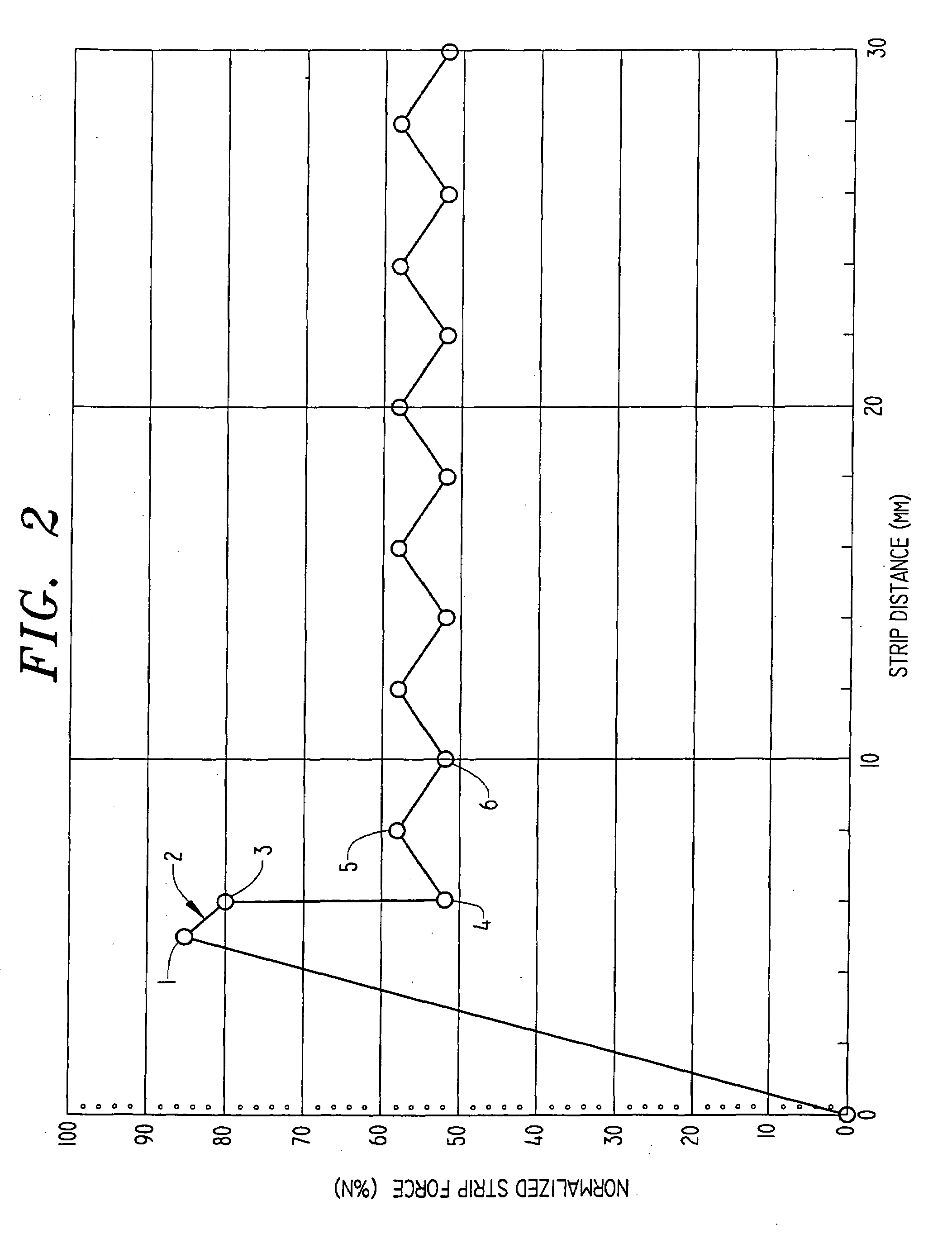
[0211]A 75 micron film of the coating material was also prepared and suitably cured. The crack propagation was then measured. A fiber pull-out friction test was also conducted, as described herein. The predicted ribbon strip cleanliness was calculated. The results are shown in Table 4.

TABLE 4Example2-4Component(Amount in % by weight of total composition)H-I-(PTGL2000-I)2-H49.24Ethoxylated Nonylphenol Acrylate Ester25.46Diphenyl(2,4,6-trimethylbenzoyl) Diphenyl3Phosphine Oxide and 2-Hydoxy-2-Methyl-1-Phenyl-1-Propanone blendLauryl Acrylate16Thiodiethylene bis(3,5-di-Tert-Butyl-4-0.5Hydroxy)hydrocinnamateH-I...

examples 3-1 through 3-4

[0302]The components shown in Table 6 were combined to form four inner primary coating compositions. Drawdowns of the inner primary coating compositions were made and then cured by exposure to UV light from a Fusion D lamp, under a nitrogen atmosphere. The crack propagation and fiber friction for each of the films were tested in the same manner as above, and the predicted strip cleanliness was calculated. The results are shown in Table 6.

TABLE 6ExampleExampleExampleExample3-13-23-33-4COMPONENT(Amount in % by weight of totalcomposition)Linear Urethane Acrylate23———Oligomer Having a Weight AverageMolecular Weight of 5000,Urethane Acrylate Oligomer—51.942.342.3H-I-PTGL2000-I-PTGL2000-I-HLauryl Acrylate—16——Ethoxylated Nonylphenol Acrylate64.425.646.246.2Glyceryl Propoxy Triacrylate8———Phenoxyethyl Acrylate——552,4,6,-Trimethyl3333PhenylbenzoylDiphenyl Phosphine OxideThiodiethylene bis (3,5-di-tert-.50.50.50.5butyl-4-hydroxy)hydrocinnamatePolyethylene / maleic anhydride.1———copolymer wax (...


PUM

PropertyMeasurementUnit
glass transition temperatureaaaaaaaaaa
tensile elongationaaaaaaaaaa
shrinkageaaaaaaaaaa

Abstract

Optical fiber coatings are disclosed having excellent ribbon stripping and adhesion behavior. The coatings are radiation-curable. The excellent stripping and adhesion behavior can be achieved by several means which include by use of additives, by use of radiation-curable oligomers having higher molecular weight, or by use of coatings having certain thermal properties. Combination of means can be employed. Stripping behavior can be measured by crack propagation and fiber friction measurements.

Description

CROSS-REFERENCE TO RELATED APPLICATIONS[0001]This application is a continuation-in-part application of co-pending U.S. patent application Ser. No. 08 / 877,585, filed Jun. 17, 1997, which is itself a continuation-in-part application of co-pending U.S. patent application Ser. No. 08 / 840,893, filed on Apr. 17, 1997, which is itself a continuation-in-part application of U.S. patent application Ser. No. 08 / 745,790 filed on Nov. 8, 1996, all of which are hereby incorporated in their entirety by reference.FIELD OF THE INVENTION[0002]The invention relates to radiation-curable inner and outer primary optical glass fiber coating compositions. The invention also relates to coated optical glass fibers and optical glass fiber assemblies. More particularly, the invention relates to a ribbon assembly having improved ribbon stripping capabilities.BACKGROUND OF THE INVENTION[0003]Optical glass fibers are usually coated with two superposed radiation-cured coatings, which together form a primary coatin...

Claims


Application Information

Patent Timeline
Patent Type & Authority Applications(United States)
IPC IPC(8): C08L83/04C03C25/10C03C25/24G02B6/44C08F2/46C08F2/48C08F2/50
CPCC03C25/1065
Inventor SZUM, DAVID M.CHAWLA, CHANDER P.PETISCE, JAMES R.VANDEBERG, JOHN T.PASTERNACK, GEORGEBISHOP, TIMOTHY E.SNOWWHITE, PAUL E.ZAHORA, EDWARD P.LAPIN, STEPHEN C.
Owner DSM IP ASSETS BV
Learn More