
Fuel Cell System and Mobile Body

a fuel cell and mobile body technology, applied in the control arrangement of battery/fuel cell, cell components, electrochemical generators, etc., can solve the problems of low power generation efficiency, limited cell voltage recovery processing, and useless auxiliary machine power consumption

Active Publication Date: 2009-07-02
TOYOTA JIDOSHA KK
View PDF1 Cites 7 Cited by
  • Summary
  • Abstract
  • Description
  • Claims
  • Application Information

AI Technical Summary

Benefits of technology

[0009]Therefore, a theme of the present invention lies in that both suppression of response delay and improvement of power generation efficiency in a fuel cell system are achieved.
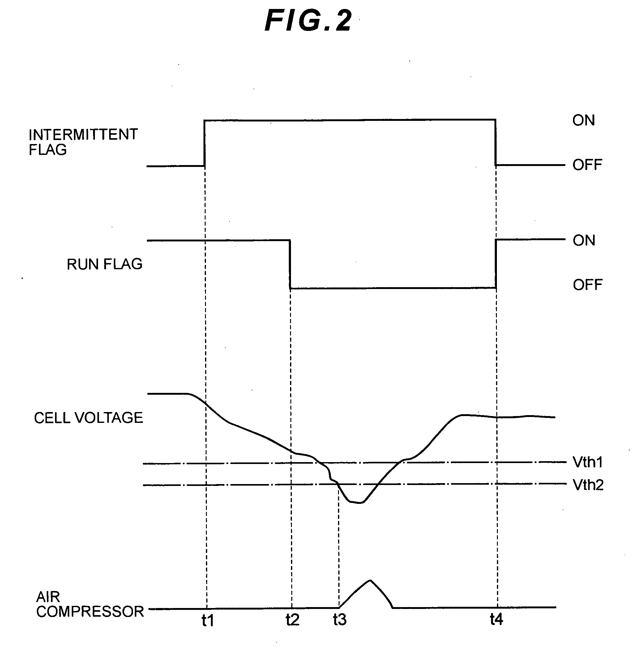
[0012]It is to be noted that it may be constituted that when the mobile body is moving, the cell voltage recovery processing executing condition is leniently set. To leniently set the cell voltage recovery processing executing condition indicates that the cell voltage recovery processing executing condition is easily satisfied.
[0015]When the power to be supplied from the power accumulation device covers the required load even during the intermittent operation, the necessity of recovering the cell voltage is small, so that the cell voltage recovery processing can be limited to suppress the decrease of the power generation efficiency due to the unnecessarily performed cell voltage recovery processing.

Problems solved by technology

However, even in a situation in which generation of load fluctuation is not expected as in a situation during stop of a vehicle (in a situation in which even if the load fluctuation occurs, response delay does not influence drivability), when processing of driving an air compressor or the like to supply an oxide gas to a fuel cell stack and recover a cell voltage is performed, an auxiliary machine power is uselessly consumed, and hence power generation efficiency is low.
The control device limits the cell voltage recovery processing during stop of the mobile body.

Method used


Image

  • Fuel Cell System and Mobile Body
  • Fuel Cell System and Mobile Body
  • Fuel Cell System and Mobile Body

Examples


Embodiment Construction

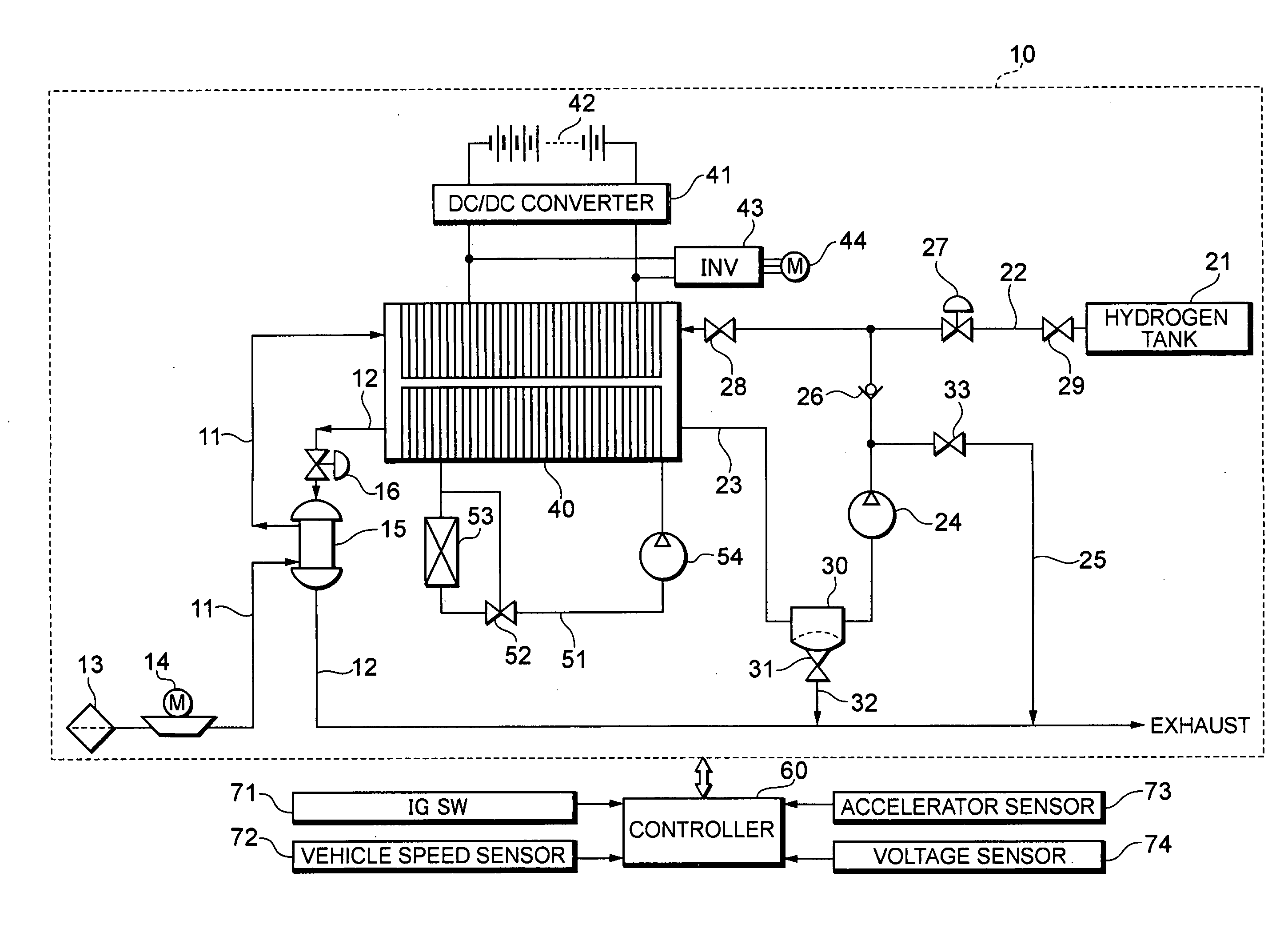
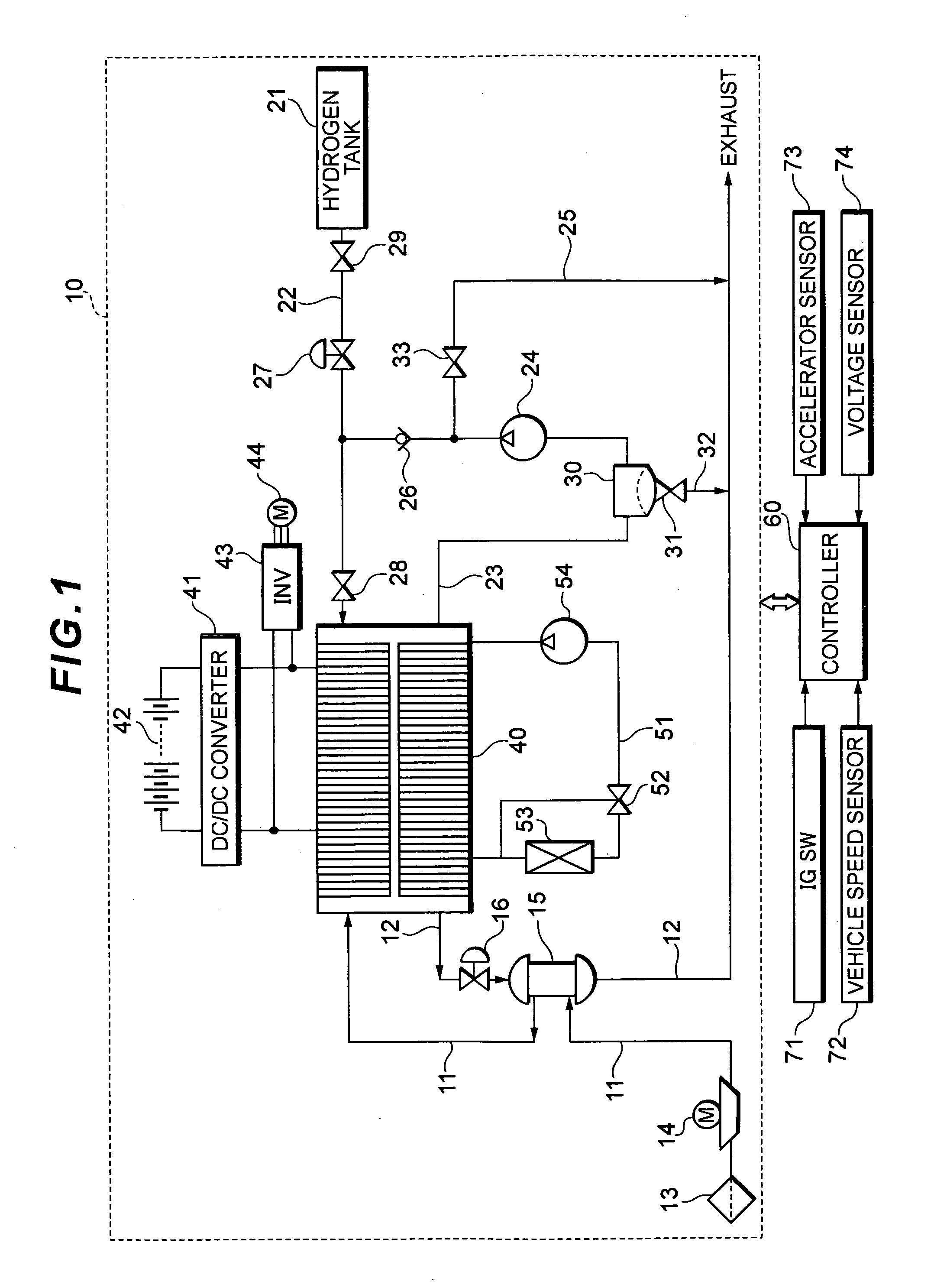
[0021]FIG. 1 is a system constitution of a fuel cell system 10 according to the present embodiment.

[0022]The fuel cell system 10 functions as a power generation system to be mounted on, for example, a fuel cell vehicle, and includes a solid polymer electrolytic fuel cell stack 40 including a stack structure in which a plurality of cells are laminated. Each cell includes a film-electrode bonded member in which an anode is arranged at one surface of an electrolytic film and in which a cathode is arranged at the other surface, and a separator provided with a gas channel (an anode gas channel, a cathode gas channel) for passing a reactive gas (a fuel gas, an oxide gas) through the film-electrode bonded member and a refrigerant channel for passing a refrigerant. The fuel cell stack 40 receives supply of a hydrogen gas (the fuel gas) at the anode, and receives an oxygen gas (the oxide gas) at the cathode to generate a power.

[0023]In the fuel cell stack 40, an oxidizing reaction of formula...


PUM

PropertyMeasurementUnit
voltageaaaaaaaaaa
cell voltageaaaaaaaaaa
poweraaaaaaaaaa

Abstract

In a mobile body, an intermittent operation to temporarily halt a cell operation is performed at a time when a request for power generation with respect to a fuel cell stack is less than a predetermined value, and recovery processing of a cell voltage is performed at a time when a cell voltage recovery processing executing condition is satisfied during the intermittent operation. When the mobile body is moving, a threshold voltage Vth1 is set as the cell voltage recovery processing executing condition. When the mobile body is stopped, a threshold voltage Vth2 is set as the cell voltage recovery processing executing condition. When the voltages are set so as to obtain a relation Vth1>Vth2, the cell voltage recovery processing can be limited during the stop of the mobile body.

Description

TECHNICAL FIELD[0001]The present invention relates to a fuel cell system in which an intermittent operation for temporarily halting a cell operation is performed at a time when a request for power generation with respect to a fuel cell stack is less than a predetermined value, and a mobile body including this system.BACKGROUND ART[0002]A fuel cell system is an energy conversion system in which a fuel gas and an oxide gas are supplied to a film-electrode bonded member to cause an electrochemical reaction, and chemical energy is converted into electric energy. Above all, in a solid polymer electrolytic fuel cell in which a solid polymer film is used as an electrolyte, compactness can easily be achieved at low cost, further the cell has a high output density, and hence an application as a power supply system to be mounted on a vehicle is expected.[0003]Furthermore, in a fuel cell vehicle on which the fuel cell system is mounted as a power source, in a high output area where power gener...

Claims


Application Information

Patent Timeline
Patent Type & Authority Applications(United States)
IPC IPC(8): H01M8/04
CPCB60L11/1887Y02T90/34H01M8/04223H01M8/04231H01M8/04559H01M8/04604H01M8/04753H01M8/04776H01M8/0488H01M8/0491H01M8/0494H01M8/04947H01M8/04955H01M16/006Y02E60/50B60L11/1892B60L58/40B60L58/33Y02T90/40Y02T10/70Y02E60/10H01M8/04228H01M8/04H02J7/00H01M8/24B60L50/50
Inventor UMAYAHARA, KENJI
Owner TOYOTA JIDOSHA KK
Learn More