
Reducing Incident Infrared Radiation Received By One Or More Infrared Detectors In A Self Checkout Point Of Sale System

a self-checkout, infrared detector technology, applied in the field of data processing, can solve the problems of complex computer systems, often providing faulty measurements in security zones, and achieve the effect of reducing incident infrared radiation

Active Publication Date: 2009-06-25
TOSHIBA GLOBAL COMMERCE SOLUTIONS HLDG
View PDF7 Cites 7 Cited by
  • Summary
  • Abstract
  • Description
  • Claims
  • Application Information

AI Technical Summary

Benefits of technology

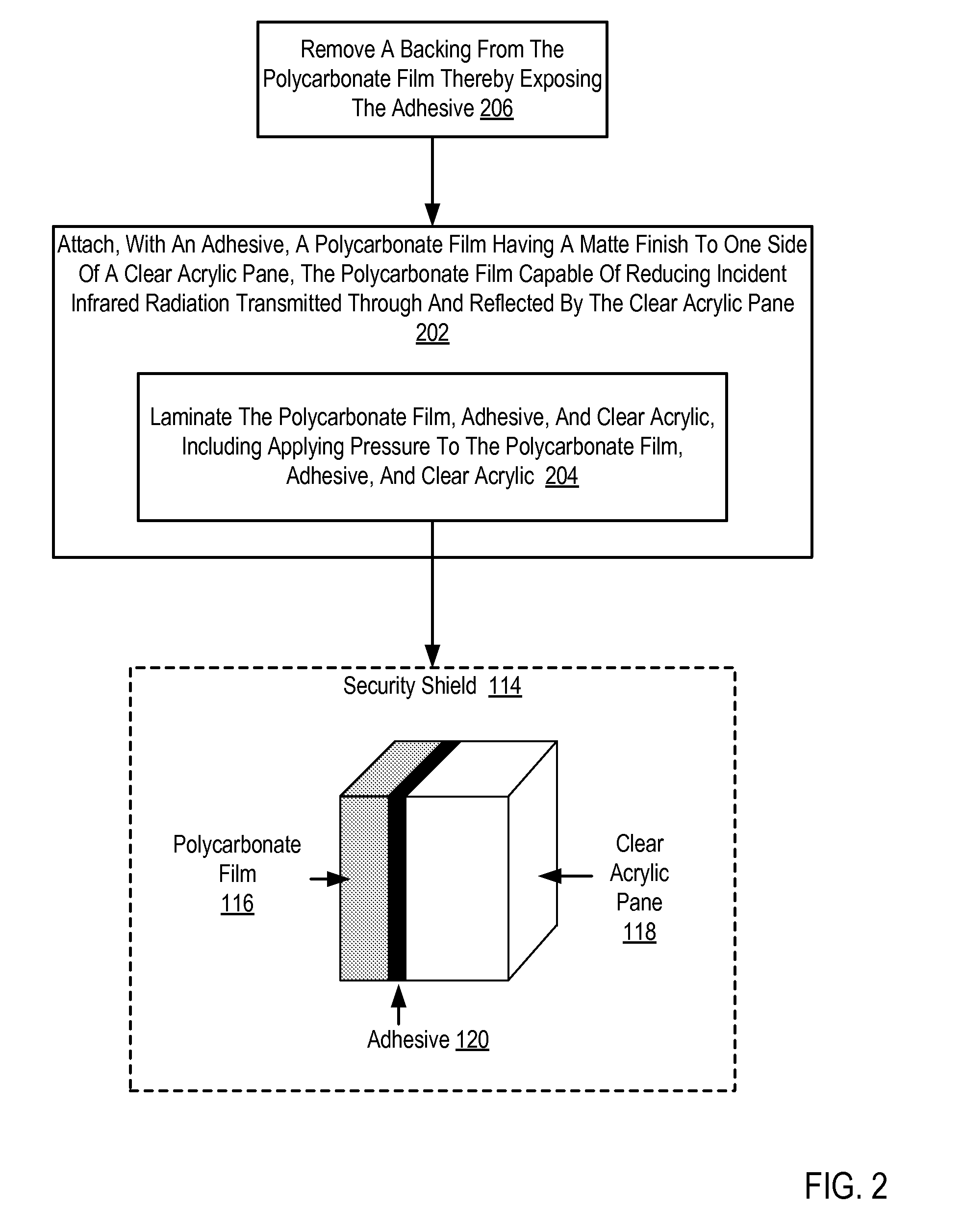
The patent describes methods and devices for reducing infrared radiation in a self-checkout POS system. The invention involves attaching a polycarbonate film with a matte finish to a clear acrylic pane using adhesive. This film is capable of reducing incident infrared radiation transmitted through and reflected by the clear acrylic pane. The invention also includes the installation of security shields on both sides of the detecting tower and emitting tower, which include a clear acrylic pane and a polycarbonate film with a matte finish. The technical effect of this invention is to enhance the security of the self-checkout POS system by reducing the amount of infrared radiation that can be detected by the system's infrared detectors.

Problems solved by technology

Since that time, computer systems have evolved into extremely complicated devices.
Due to reflection and transmission of ambient light, stray infrared radiation from infrared emitters, and stray infrared radiation from other sources, the security zone often provides faulty measurements by the combination of infrared emitters and detectors.

Method used


Image

  • Reducing Incident Infrared Radiation Received By One Or More Infrared Detectors In A Self Checkout Point Of Sale System
  • Reducing Incident Infrared Radiation Received By One Or More Infrared Detectors In A Self Checkout Point Of Sale System
  • Reducing Incident Infrared Radiation Received By One Or More Infrared Detectors In A Self Checkout Point Of Sale System

Examples


Embodiment Construction

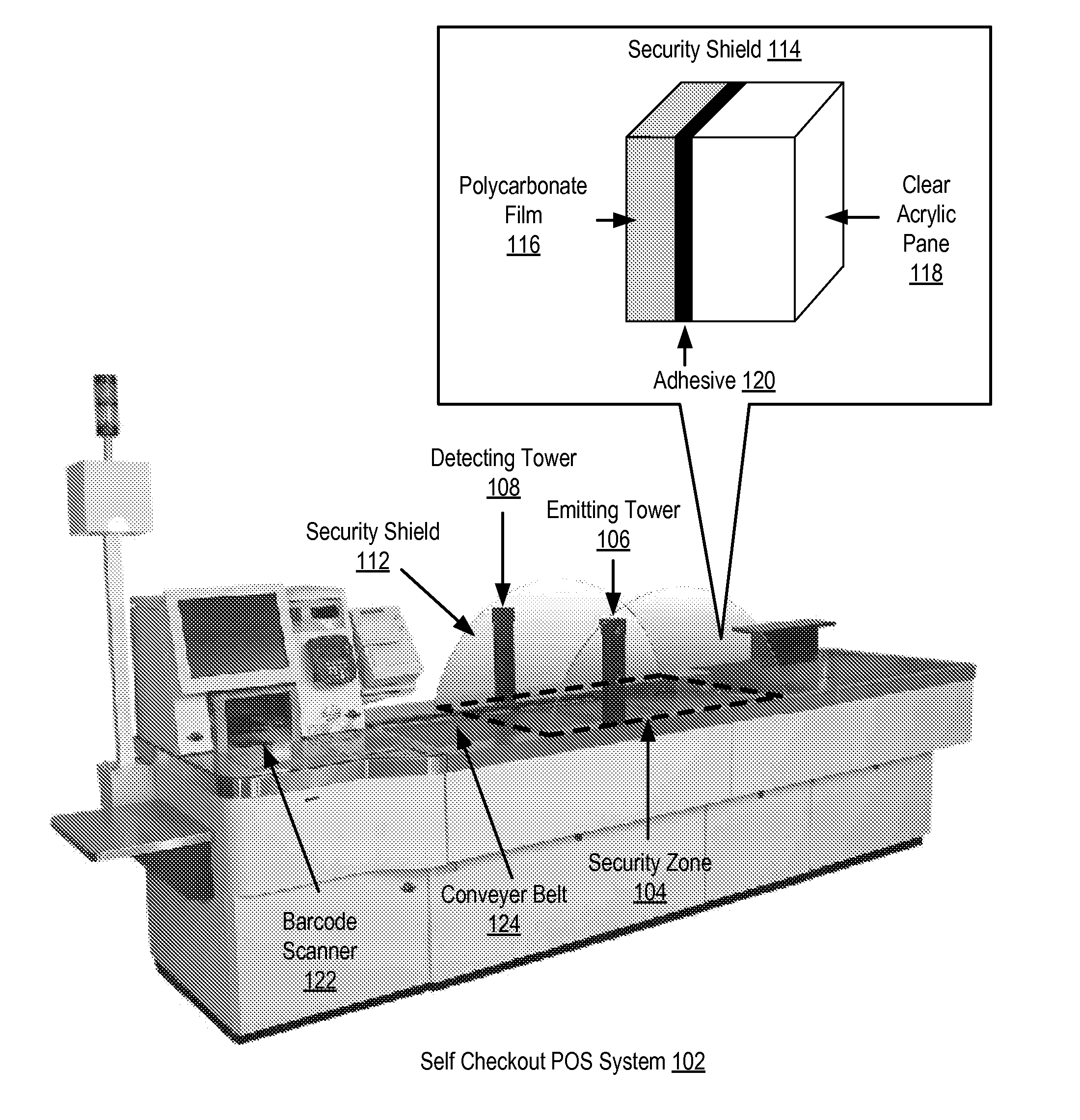
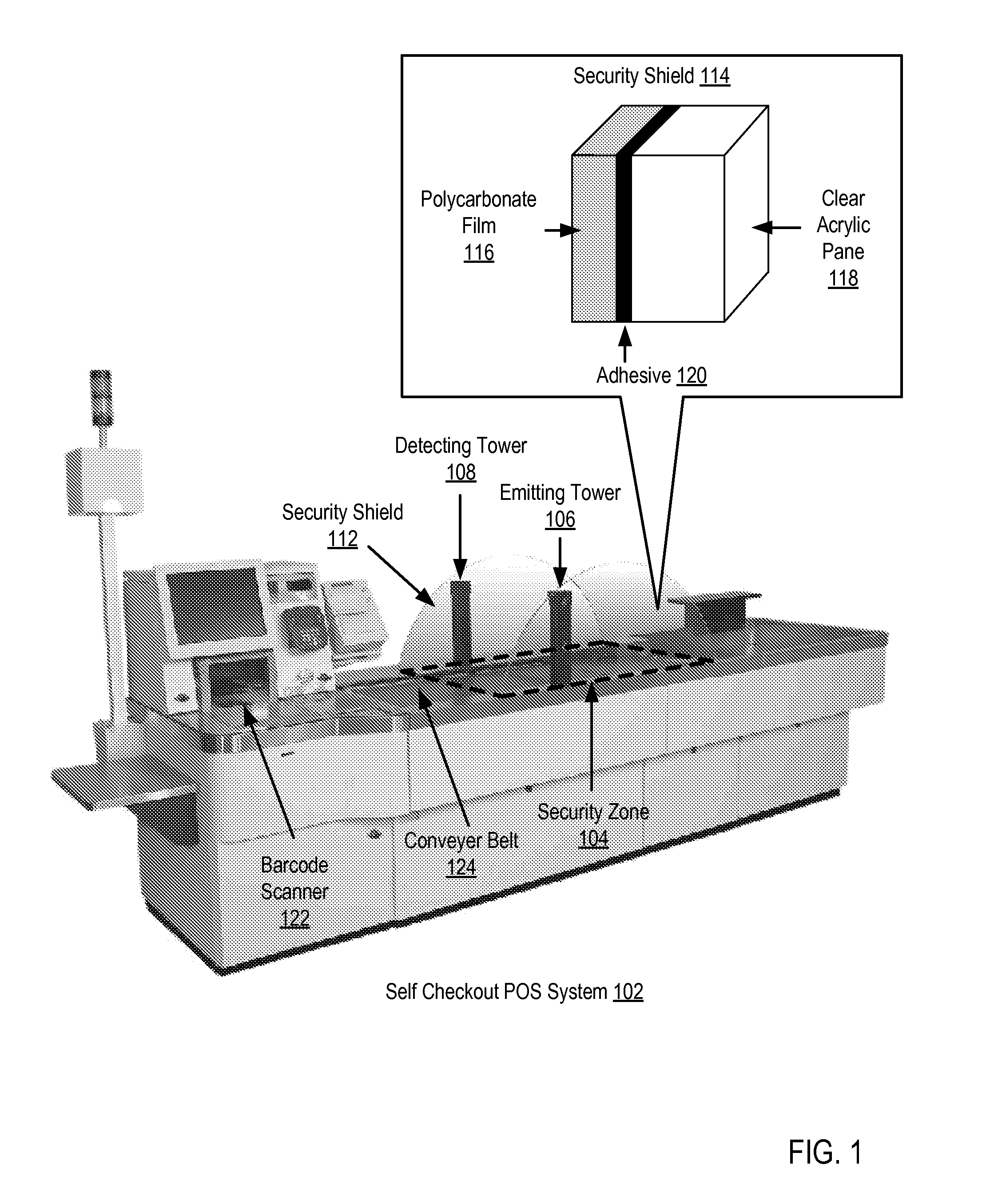
[0013]Exemplary self checkout point of sale (‘POS’) systems, security shields, and methods for reducing incident infrared radiation received by one or more infrared detectors in a self checkout point of sale system in accordance with the present invention are described with reference to the accompanying drawings, beginning with FIG. 1. FIG. 1 sets forth an exemplary self checkout POS system (102) for reducing incident infrared radiation received by one or more infrared detectors according to embodiments of the present invention. The system of FIG. 1 includes a security zone (104), represented for clarity by a dotted line. The exemplary security zone (104) of FIG. 1 is an area in which measurements of retail items are taken for verification when the item's barcode is scanned for purchase. In the system of FIG. 1, for example, the height of an item may be measured while the item travels down the conveyer belt (124) toward the barcode scanner (122). When the item's barcode is scanned, ...


PUM

PropertyMeasurementUnit
wavelengthaaaaaaaaaa
thicknessaaaaaaaaaa

Abstract

A self checkout POS system including a security zone; an emitting tower including one or more infrared emitters; a detecting tower including one or more infrared detectors, the detecting tower located on a side of the security zone opposite the side on which the emitting tower is located, the infrared detectors of the detecting tower aligned for reception of infrared radiation emitted by the infrared emitters of the emitting tower; a security shield installed on one side of the detecting tower; and a security shield installed on one side of the emitting tower, the security shield installed on one side of the emitting tower including: a clear acrylic pane; and a polycarbonate film having a matte finish, the polycarbonate film laminated to the clear acrylic pane with an adhesive, the polycarbonate film capable of reducing incident infrared radiation transmitted through and reflected by the clear acrylic pane.

Description

BACKGROUND OF THE INVENTION[0001]1. Field of the Invention[0002]The field of the invention is data processing, or, more specifically, security shields, self checkout point of sale (‘POS’) systems, and methods for manufacturing security shields for reducing incident infrared radiation received by one or more infrared detectors in a self checkout point of sale system.[0003]2. Description Of Related Art[0004]The development of the EDVAC computer system of 1948 is often cited as the beginning of the computer era. Since that time, computer systems have evolved into extremely complicated devices. Today's computers are much more sophisticated than early systems such as the EDVAC. Computer systems typically include a combination of hardware and software components, application programs, operating systems, processors, buses, memory, input / output devices, and so on. As advances in semiconductor processing and computer architecture push the performance of the computer higher and higher, more s...

Claims


Application Information

Patent Timeline
Patent Type & Authority Applications(United States)
IPC IPC(8): B32B3/02B32B27/36B32B37/12B32B38/04
CPCB32B38/0004Y10T428/26B32B2309/105B32B2333/08B32B2369/00G06Q30/0603G07G1/0018B32B7/12B32B27/08B32B27/308B32B27/365B32B2250/24B32B2307/71B32B2457/00Y10T156/10Y10T156/1052B32B2307/416Y10T428/31507
Inventor DICKOVER, WESLEY D.SLOOP, III, CHARLES C.
Owner TOSHIBA GLOBAL COMMERCE SOLUTIONS HLDG
Learn More