Control apparatus for hybrid driving apparatus

Inactive Publication Date: 2009-06-25
TOYOTA JIDOSHA KK
View PDF2 Cites 19 Cited by
  • Summary
  • Abstract
  • Description
  • Claims
  • Application Information

AI Technical Summary

Benefits of technology

[0006]It is therefore an object of the present invention to provide such a control apparatus for a hybrid driving apparatus that can prevent a reduction in power performance and comfortable performance of a vehicle.
[0040]Here, according to this aspect, the engaging device is controlled by the controlling device such that the specified large and small extent of the decelerating operation correspond to the small and large magnitude of the frictional force, respectively. In other words, in accordance with at least an increase in the extent of the decelerating operation, the friction force between the engagement elements is reduced in a binary, stepwise, or continuous manner. Therefore, it is more certain that the reduction in power performance and comfortable performance can be prevented, compared to the case where the engaging device has such a structure that the engagement force between the first and second engagement elements can be indirectly changed by increasing the output torque of the first electric motor or the like, i.e. the structure that it is hard to actively control the engagement force, such as a engagement type engaging apparatus.

Problems solved by technology

Therefore, for example, in circumstances that a driver may perform a sudden breaking operation, such as avoiding a vehicle ahead or an obstacle ahead, there can be such problems that the combustion rotational speed is rapidly reduced and that the power performance of the hybrid vehicle is reduced.
In particular, if the combustion rotational speed falls below a self-rotatable rotational speed or in similar cases, the internal combustion cannot keep the self-rotational state, and not only the reduction in power performance but also a reduction in comfortable performance are likely actualized, such as an increase in knocking and engine stall (or engine failure).
In other words, the conventional technology has such a technical problem that the power performance or comfortable performance of the hybrid vehicle is likely reduced in the sudden braking.

Method used


Image

  • Control apparatus for hybrid driving apparatus
  • Control apparatus for hybrid driving apparatus
  • Control apparatus for hybrid driving apparatus

Examples


first embodiment

[0052]

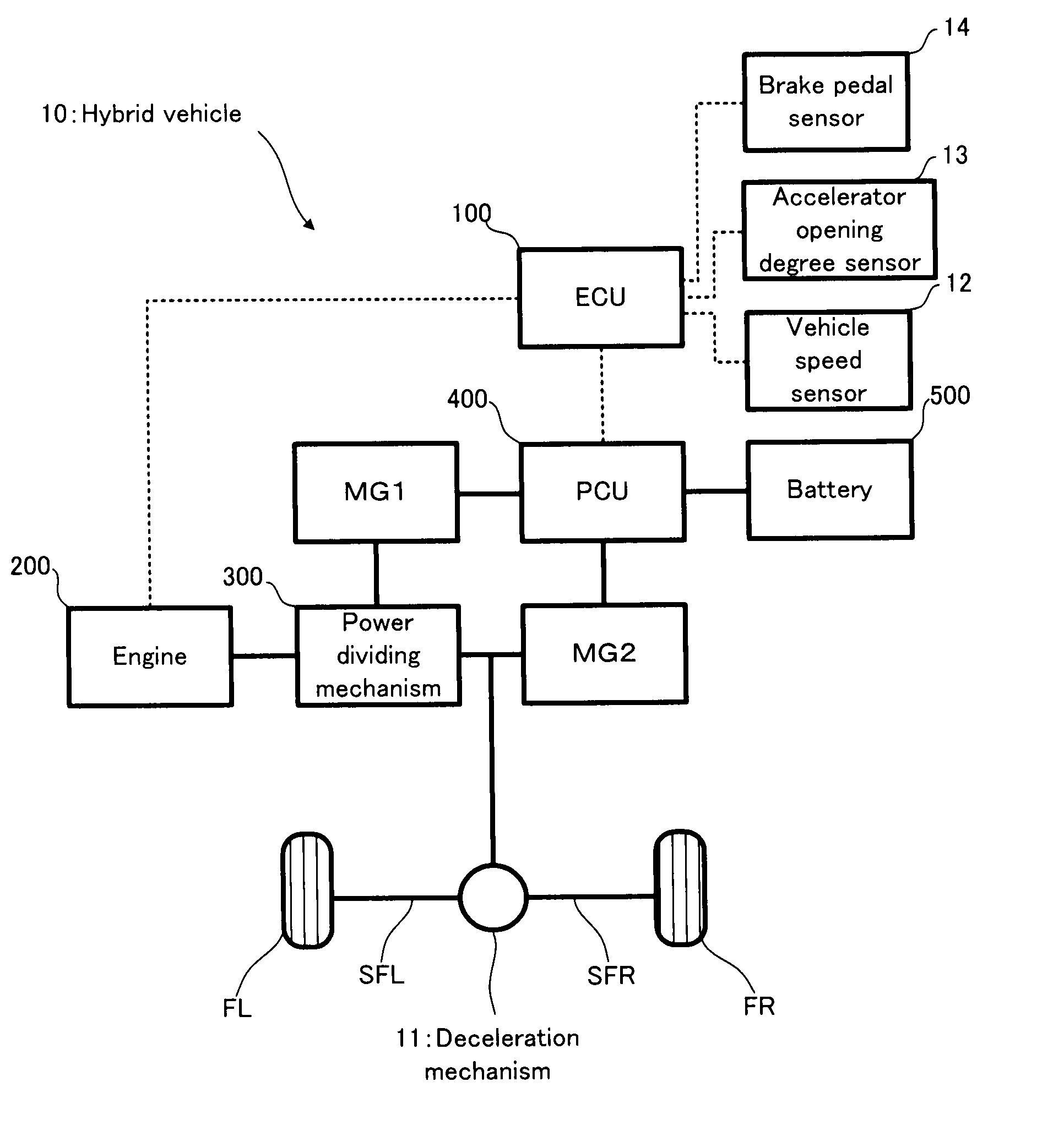
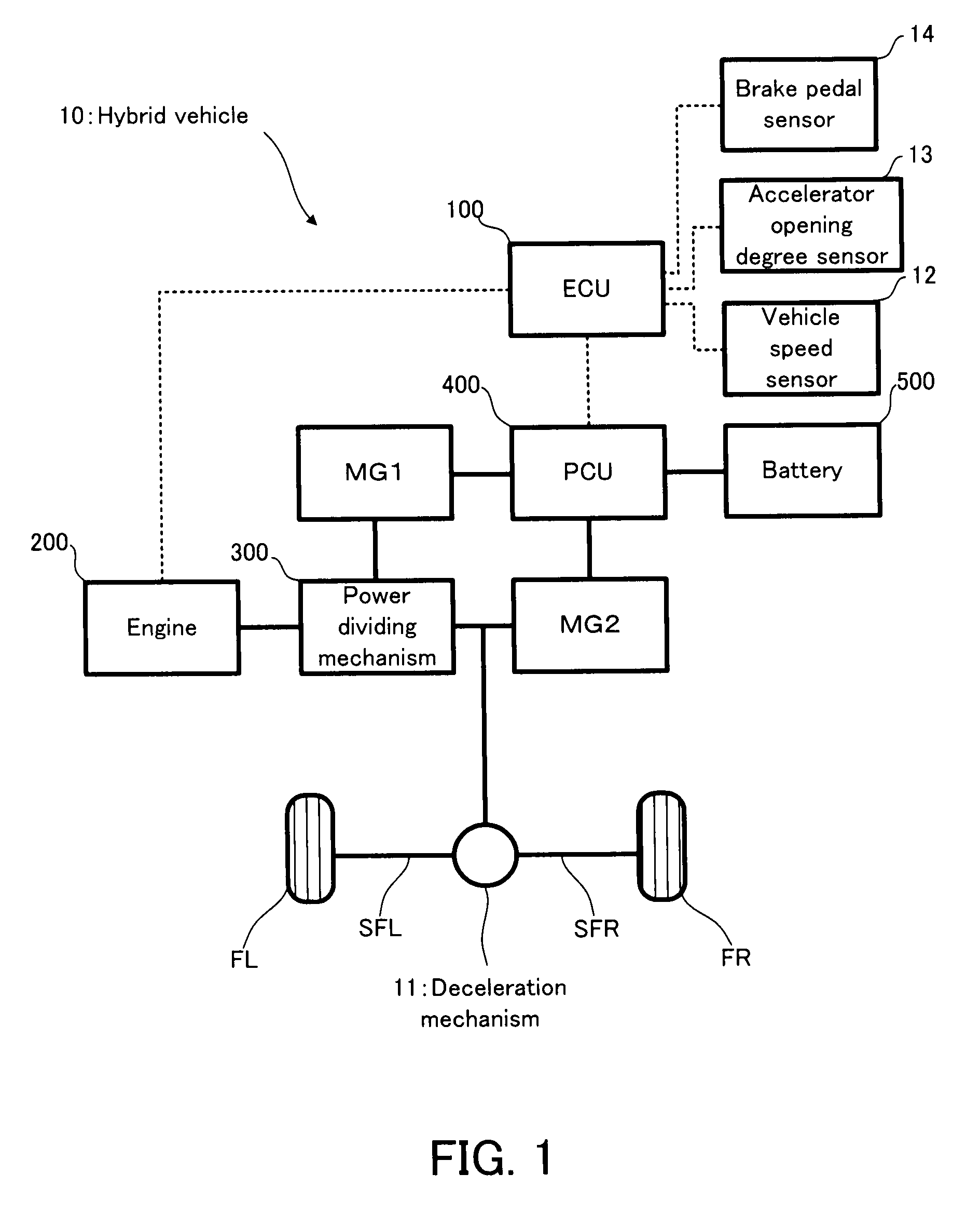
[0053]Firstly, with reference to FIG. 1, an explanation will be given on the structure of a hybrid vehicle 10 in a first embodiment of the present invention.

[0054]FIG. 1 is a schematic configuration diagram conceptually showing the structure of the hybrid vehicle 10.

[0055]In FIG. 1, the hybrid vehicle 10 is provided with an ECU 100; an engine 200; a power dividing mechanism 300; a motor generator MG1 (hereinafter abbreviated to a “MG1”, as occasion demands); a motor generator MG2 (hereinafter abbreviated to a “MG2”, as occasion demands); a PCU (Power Control Unit) 400; a battery 500; and a vehicle speed sensor 600. The hybrid vehicle 10 is one example of the “vehicle” of the present invention.

[0056]The ECU 100 is provided with a CPU (Central Processing unit), a ROM (Read Only Memory), a RAM, and the like. The ECU 100 is an electronic control unit, adapted to control the entire operation of the hybrid vehicle 10, and it is one example of the “control apparatus for the hybrid dr...

second embodiment

[0140]As one example of the “power dividing device” of the present invention, the first embodiment illustrates the power dividing mechanism 300 obtained by combining the single pinion type planetary gear mechanism and the double pinion type planetary gear mechanism; however, the construction that the power dividing device of the present invention can adopt is not limited to the power dividing mechanism 300 as long as it can realize at least the stepless speed-change mode and the fixed speed-change mode. Now, with reference to FIG. 7 and FIG. 8, other construction examples of the power dividing device will be explained as a second embodiment of the present invention. FIG. 7 is a schematic configuration diagram conceptually showing the structure of a power dividing mechanism 800. FIG. 8 is a schematic configuration diagram conceptually showing the structure of a power dividing mechanism 900. Incidentally, in FIG. 7 and FIG. 8, the repeated points of FIG. 3 carry the same reference num...


PUM


Abstract

In a hybrid vehicle, an ECU performs speed-change control and selectively changes a speed-change mode between a stepless speed-change mode and a fixed speed-change mode in accordance with the travel condition of the hybrid vehicle. At this time, in the condition that the fixed speed-change mode is selected, if an accelerator off operation is performed, a release preparing process is performed, and a reaction element which receives the reaction torque of engine torque in a power dividing mechanism is changed to a sun gear on a motor generator side. Moreover, if an accelerator off speed or a brake pedal operation amount exceeds its own reference value, the speed-change mode is transferred into the stepless speed-change mode, predictively and unconditionally, before a normal speed-change condition is met.

Description

BACKGROUND OF THE INVENTION[0001]1. Field of the Invention[0002]The present invention relates to a control apparatus for a hybrid driving apparatus, which is equipped with an internal combustion and an electric motor as the power source of a vehicle.[0003]2. Description of Related Art[0004]As this type of driving apparatus for a hybrid vehicle, the following apparatus has been suggested: a driving apparatus provided with a brake, in which a power source, an output member, and a first motor generator are connected to a power transfer mechanism, provided with a plurality of pairs of differential mechanisms, and in which the rotation of any of the rotational elements of the power transfer mechanism is stopped, to thereby fix a ratio of the number of rotations between the power source and the output member in an overdrive state (e.g. refer to Japanese Patent Application Publication Laying Open No. 2004-345527). According to the driving apparatus for the hybrid vehicle disclosed in Japan...

Claims


Application Information

Patent Timeline
IPC IPC(8): B60W10/10B60W20/00B60K6/365B60K6/445B60L50/16B60W10/08F16H3/72
CPCB60K1/02Y02T10/6239B60K6/445B60L2240/421B60L2240/423B60L2240/486B60W10/02B60W10/08B60W10/115B60W20/00B60W30/18109B60W2510/081B60W2540/106B60W2540/12B60W2710/083B60W2710/1011F16H2037/0873Y02T10/642Y02T10/84B60K6/365Y02T10/62Y02T10/64B60W20/30B60W10/10
Inventor EBUCHI, HIROAKIHIRATA, MOTOJI
Owner TOYOTA JIDOSHA KK
Why Eureka
Try Eureka