
Multi-axis robot for high-speed applications

a multi-axis, robot technology, applied in the direction of programmed manipulators, lifting devices, friction gearings, etc., can solve the problems of limited positioning accuracy, limited dynamic behavior, limited dynamic behavior, etc., to increase stability and rigidity, and keep the effect of stability

Active Publication Date: 2009-06-18
PILZ (COMPANY)
View PDF8 Cites 24 Cited by
  • Summary
  • Abstract
  • Description
  • Claims
  • Application Information

AI Technical Summary

Benefits of technology

[0008]In view of the above, it is an object of the present invention to provide a multi-axis robot for high-speed applications, which is lightweight, efficient and inexpensive to implement. It is another object of the present invention to provide a multi-axis robot of the belt drive design having an increased positioning accuracy.

Problems solved by technology

Positioning accuracy, however, is limited with this known design, because the H-belt drive systems are susceptible to undesired rotations of the crossbar around its longitudinal axis and around the vertical Z-axis.
Positioning inaccuracies resulting from such rotations may cause problems, in particular, if the tool carrier is moved very quickly, which should be a domain of this kind of robot design.
Again, however, the proposed designs are susceptible to positioning inaccuracies as a result of undesired rotations of the crossbar.
In order to allow movements along and around three or more axes, however, these robot designs require motor drives to be moved together with the tool carrier, which limits the dynamic behavior and / or requires high-power drive systems.

Method used


Image

  • Multi-axis robot for high-speed applications
  • Multi-axis robot for high-speed applications
  • Multi-axis robot for high-speed applications

Examples


Embodiment Construction

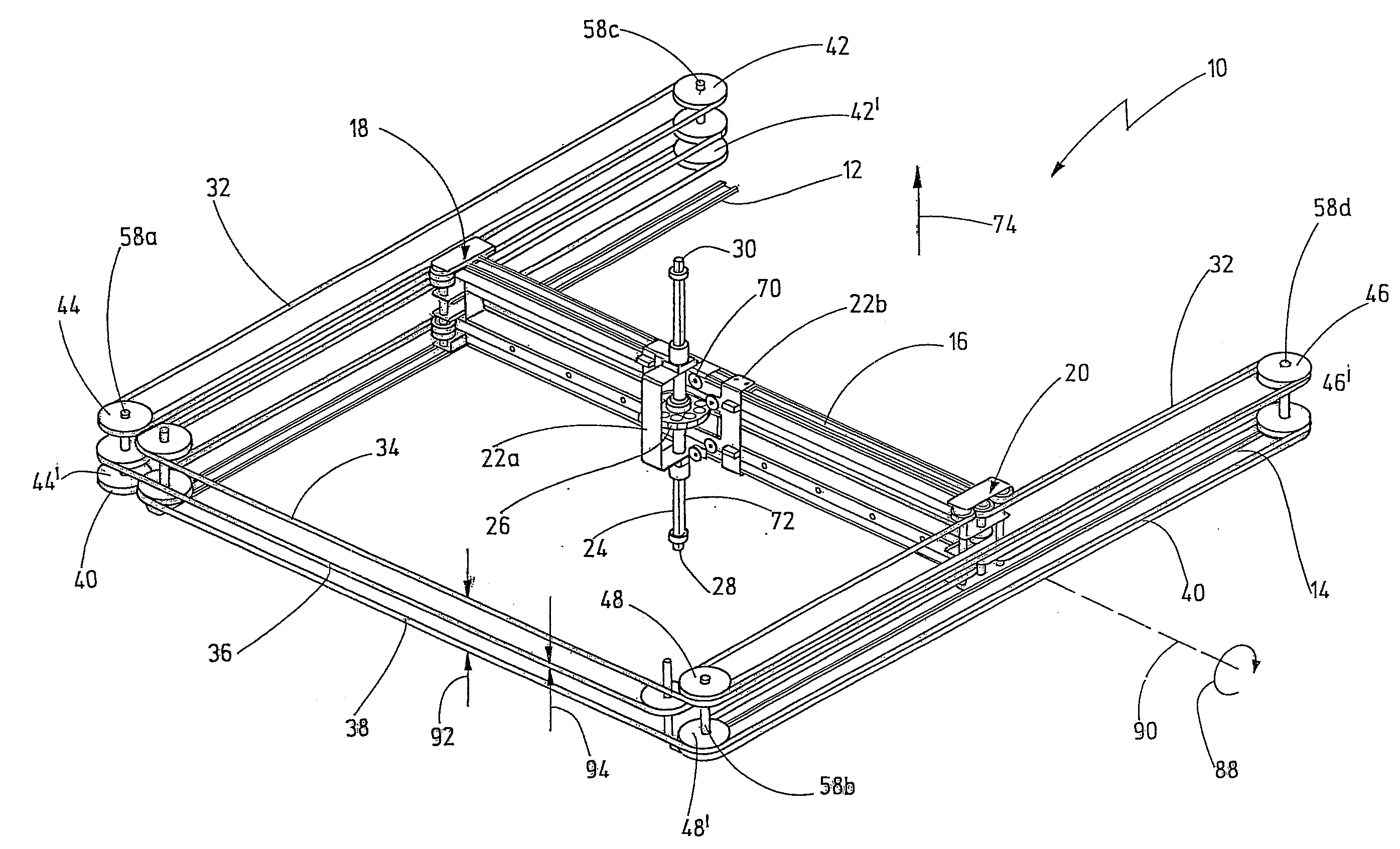
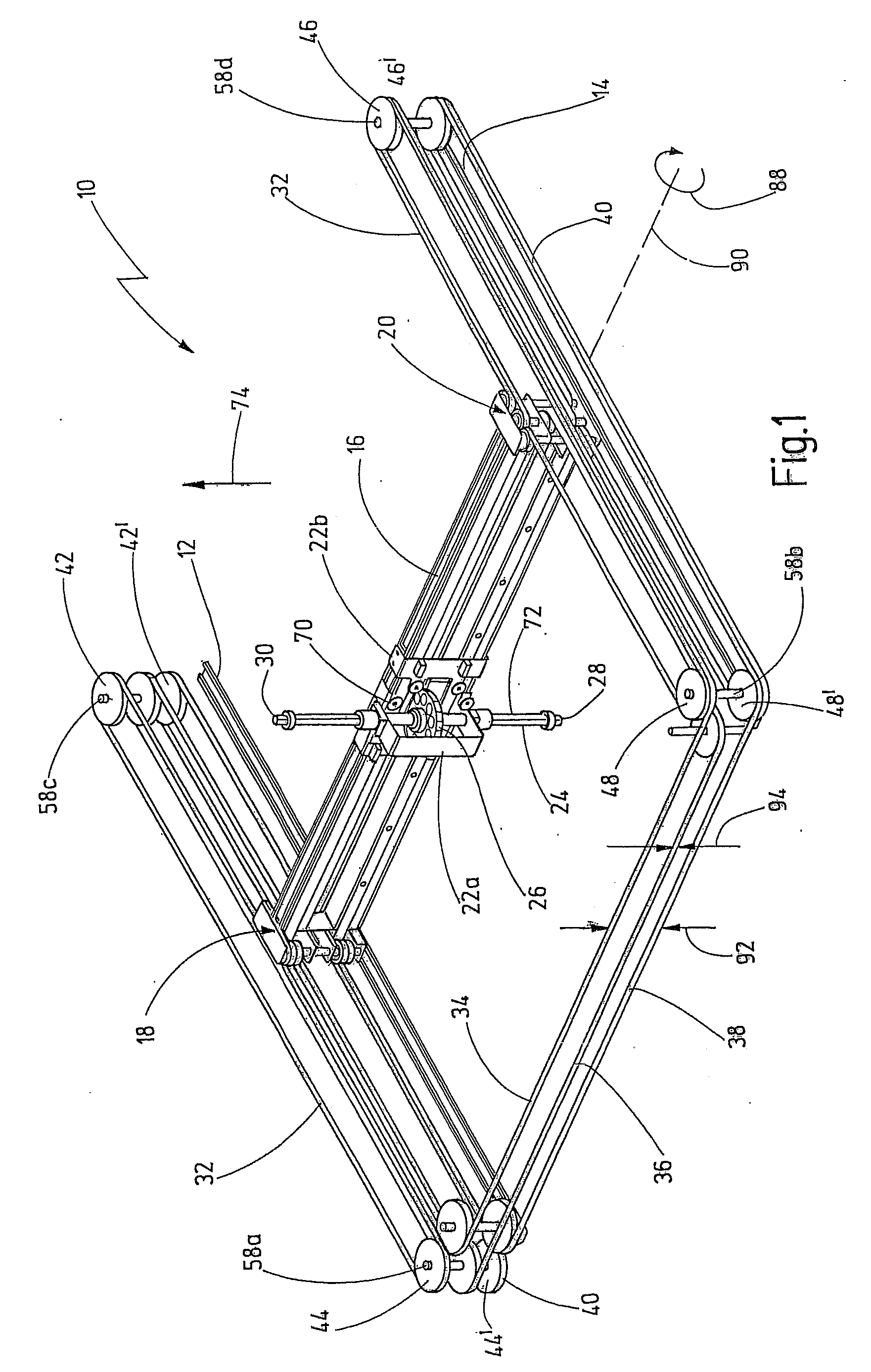
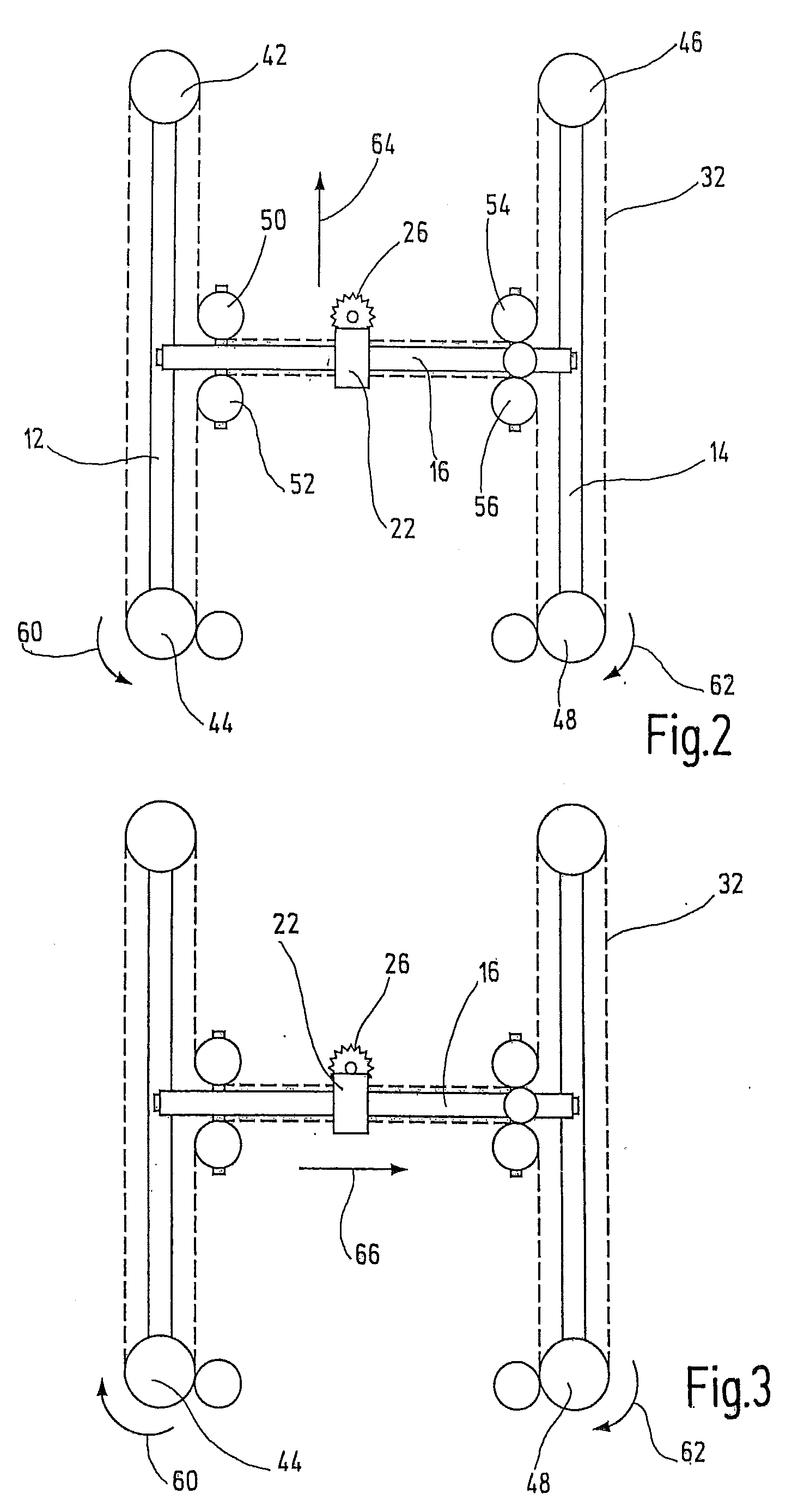
[0039]In FIG. 1, essential parts of an embodiment of the new robot are designated by reference number 10 in total. For sake of clarity, only parts of the new robot design, which are essential for the present invention, are shown here in detail. It goes without saying that the new robot actually comprises further parts not shown here, such as a general support structure, motor drives, housing parts and / or cover sheets and a controller for controlling the movements described later on. In a typical embodiment, the new robot comprises a substantially rectangular frame supported on four legs, with one leg on each corner of the frame. The frame supports two guide rails 12, 14, pulleys and the motor drives (not shown here in detail). The height of the legs and the length and width of the rectangular support frame might be chosen as appropriate for a desired application.

[0040]The new robot 10 also comprises a crossbar 16 having a first end 18 and a second end 20. The first end is supported ...


PUM


Abstract

A multi-axis robot for high-speed applications comprises a first and a second guide rail arranged substantially parallel to each other for defining a first axis of motion. A crossbar having a first end and a second end is moveably supported on the guide rails. A carriage is moveably coupled to the crossbar for moving along a second axis of motion. A first drive system having first and second drives and a first belt running along a first H-shaped belt path provides for a movement of the carriage along the first and second axis of motion. Second and third belts extend at least partially along the crossbar and the guide rails. The second and third belts run along different second and third belt paths, with one of the second and third belts entering the crossbar with a right-hand turn and leaving the crossbar with a left-hand turn, and the other one of the second and third belts entering the crossbar with a left-hand turn and leaving the crossbar with a right-hand turn.

Description

CROSSREFERENCES TO RELATED APPLICATIONS[0001]This application is filed in accordance with the Paris Convention and claims priority from European patent application 07 021 907.6 filed on Nov. 12, 2007 with the European Patent Office. The entire content of this priority application is incorporated herein by reference.BACKGROUND OF THE INVENTION[0002]The present invention relates to a multi-axis robot for high-speed applications, and, more particularly, to a multi-axis robot comprising a first and a second guide rail arranged substantially parallel to each other for defining a first axis of motion, and a crossbar for defining a second axis of motion.[0003]German patent application DE 44 44 523 A1 discloses a multi-axis robot using three belt drive systems for moving a tool carrier along three orthogonal axes X, Y, Z, and for rotating the tool carrier about one of these axes. The tool carrier is arranged on a carriage, which in turn is moveably supported on a crossbar. Each end of the c...

Claims


Application Information

Patent Timeline
Patent Type & Authority Applications(United States)
IPC IPC(8): B66C23/00
CPCB25J9/026B25J9/104Y10T74/18848F16H2019/069Y10T74/20354F16H19/06
Inventor DUJARDIN, PAUL-ERIC
Owner PILZ (COMPANY)
Learn More