Tool holder dampening system
a dampening system and tool holder technology, applied in the field of rotary cutting machines, can solve the problems of not necessarily being able to achieve metal-to-metal contact, though preferable, and achieve the effect of facilitating complete insertion of the tool holder into the spindle, eliminating harmonic resonance, and maintaining the cleanliness of the spindle/tool holder combination
- Summary
- Abstract
- Description
- Claims
- Application Information
AI Technical Summary
Benefits of technology
Problems solved by technology
Method used
Image
Examples
second embodiment
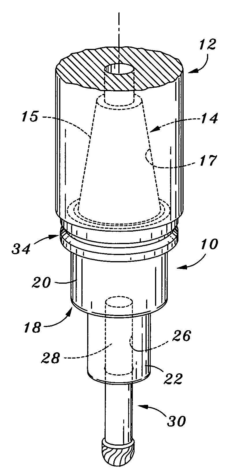
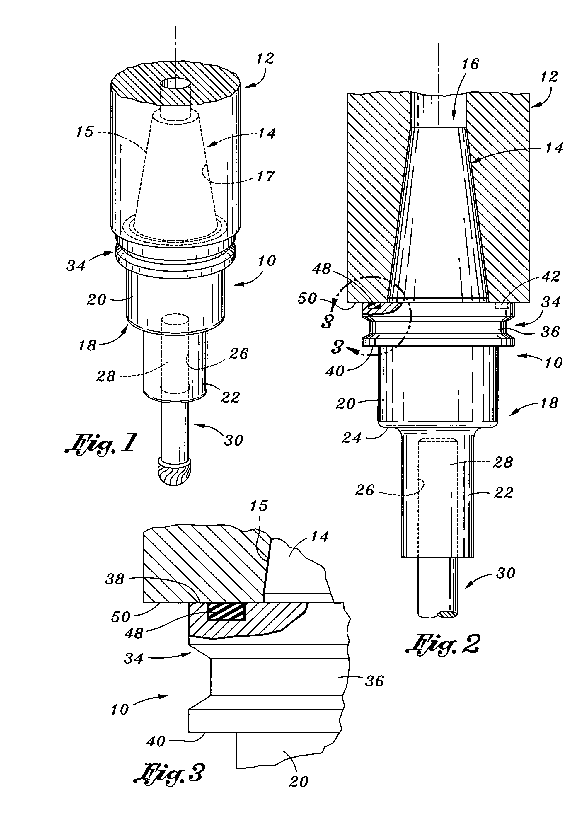
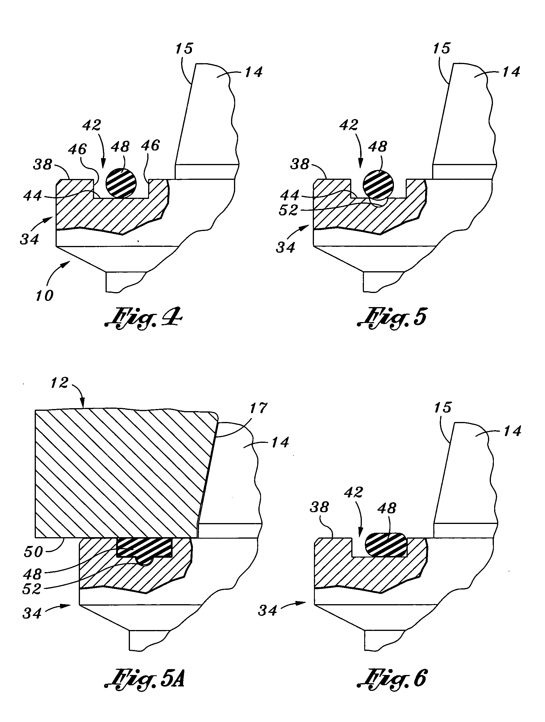
[0047]Referring now to FIG. 7, there is shown a tool holder 10a constructed in accordance with the present invention. The tool holder 10a is structurally identical to the above-described tool holder 10, with the distinction between the tool holders 10, 10a lying in the inclusion of additional dampening members 54 within the shank portion 14a of the tool holder 10a. More particularly, the tool holder 10a is preferably formed to include a plurality of continuous channels or grooves 56 which are formed in the tapered outer surface 15a of the shank portion 14a in spaced, generally parallel relation to each other and to the flange portion 34a. Disposed within each of the grooves 56 is a respective one of the dampening members 54. As will be recognized by those of ordinary skill in the art, due to the tapered configuration of the shank portion 14a, the circumference of the groove 56 disposed closest to the flange portion 34a exceeds the circumference of the groove 56 disposed furthest fro...
third embodiment
[0056]Referring now to FIG. 10, there is shown a tool holder 10b which is constructed in accordance with the present invention and is also adapted for use in the rotating spindle 12. The tool holder 10b comprises a cutting tool mounting portion 18b. The mounting portion 18b may have a cylindrically configured upper section 20b, and a cylindrically configured lower section 22b. The lower section 22b extends axially from the upper section 20b, and has an outer diameter which is less than that of the upper section 20b such that an annular shoulder 24b is defined between the upper and lower sections 20b, 22b. Extending axially within the lower section 22b is a central aperture 26b which is adapted to receive the shank portion 28 of the cutting tool 30. It will be recognized that the mounting portion 18b may be of uniform diameter rather than including the differently sized upper and lower sections 20b, 22b described above and shown in FIG. 10.
[0057]The tool holder 10b further comprises ...
fourth embodiment
[0065]Referring now to FIG. 12, a fourth embodiment illustrating an alternate interface between the distal end surface 50c of the rotating spindle 12c and the top surface 38 of the flange portion 34 is shown. In particular, the distal end surface 50c of the rotating spindle 12c may define an inner peripheral portion 94 and an outer peripheral portion 96. The inner peripheral portion 94 and the outer peripheral portion 96 may be separated by an annular groove 98 in which a dampening member 100 may be disposed. The inner peripheral portion 94 may be offset from the outer peripheral portion 96 so as to leave a vertical gap 99 between the inner peripheral portion 94 and the top surface 38 of the flange portion 34. By way of example and not limitation, the vertical gap 99 may be about 0.020 inches. The dampening member 100 may be sized and configured to the annular groove 98 in a similar proportion and manner that the dampening member 48 is sized and configured to the groove 42 shown in ...
PUM
| Property | Measurement | Unit |
|---|---|---|
| elastomeric | aaaaa | aaaaa |
| depth | aaaaa | aaaaa |
| height | aaaaa | aaaaa |
Abstract
Description
Claims
Application Information
 - R&D
- Intellectual Property
- Life Sciences
- Materials
- Tech Scout
- Unparalleled Data Quality
- Higher Quality Content
- 60% Fewer Hallucinations
Browse by: Latest US Patents, China's latest patents, Technical Efficacy Thesaurus, Application Domain, Technology Topic, Popular Technical Reports.
© 2025 PatSnap. All rights reserved.Legal|Privacy policy|Modern Slavery Act Transparency Statement|Sitemap|About US| Contact US: help@patsnap.com


