Eureka AIR delivers breakthrough ideas for toughest innovation challenges, trusted by R&D personnel around the world.

Space efficient hybrid air purifier

a technology of air purifier and hybrid collector, which is applied in the field of space efficient and hybrid collector, can solve the problems of increasing the energy needed to move air through the filter media, increasing the impediment to flow, and high pressure drop, and achieves the effect of low cost and high filtering efficiency

Inactive Publication Date: 2009-06-18
KRIGMONT HENRY
View PDF79 Cites 12 Cited by
  • Summary
  • Abstract
  • Description
  • Claims
  • Application Information

AI Technical Summary

Benefits of technology

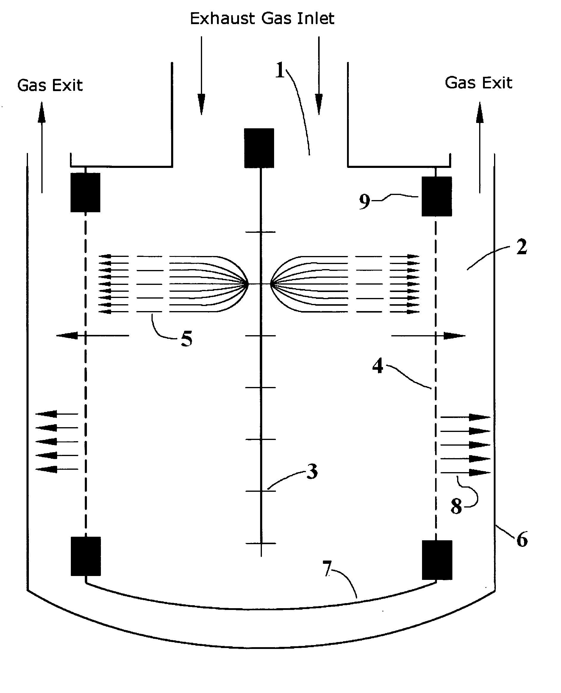
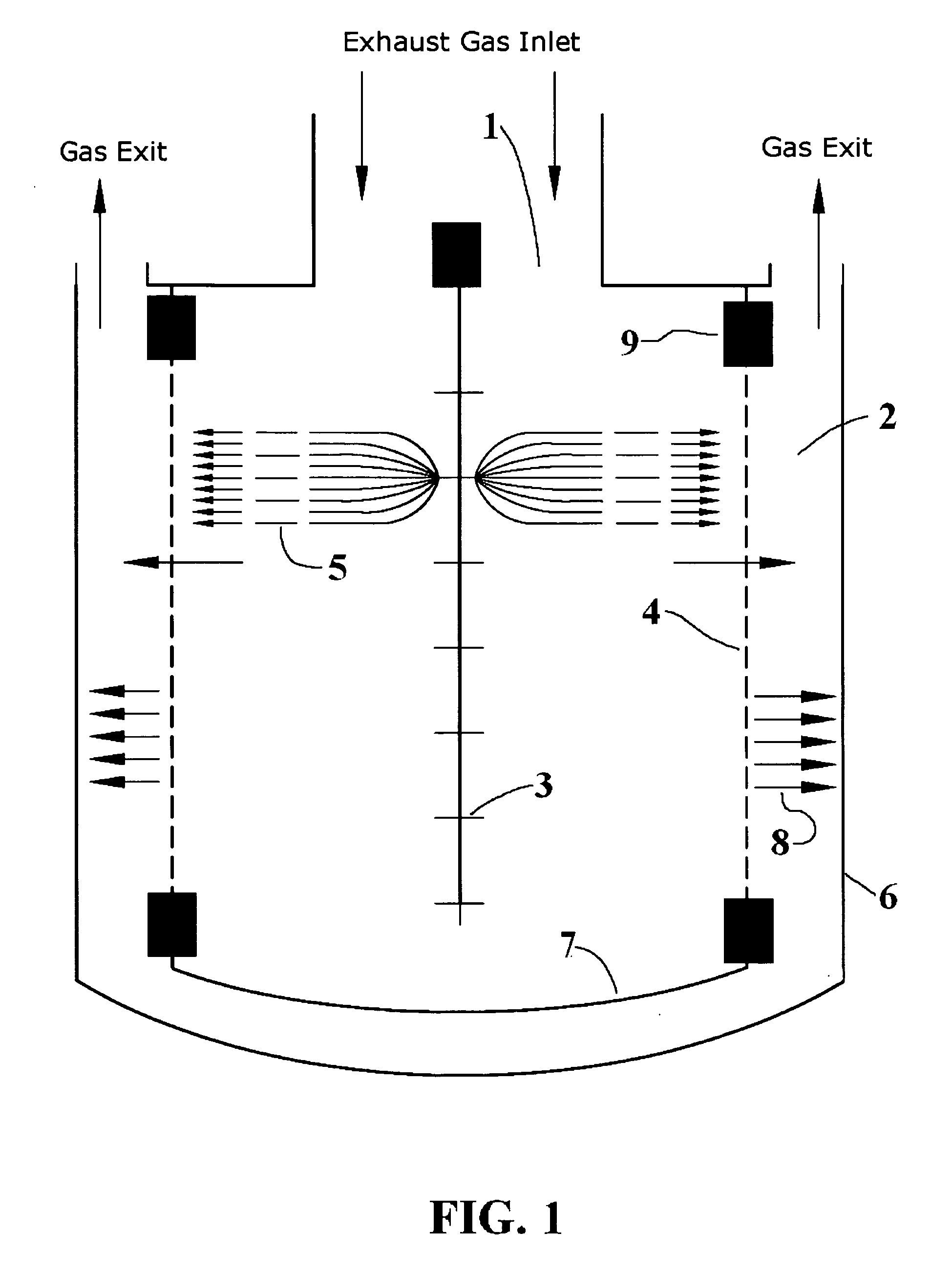
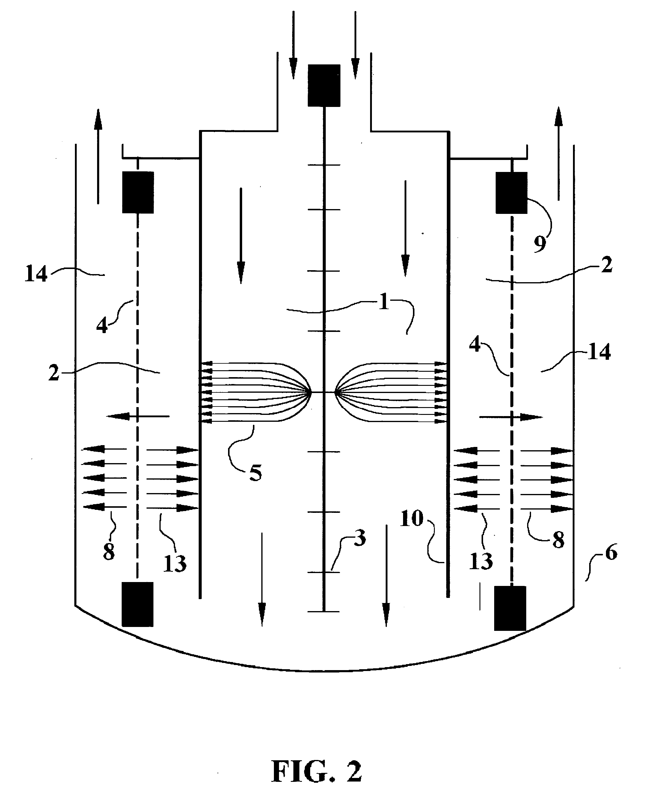
[0015]The present invention relates to a compact, hybrid collector that overcomes the deficiencies of the prior art that can be used in air purifying, a vehicle emissions control system or in any other application where space and lower cost is important. Other embodiments of the present invention can be used to achieve ultra high filtering efficiency for applications in clean rooms, surgical suites or any other application requiring ultra-clean air. Additional embodiments of the present invention provide for subsequent purified air decontamination from chemical and biological agents by incorporating ultraviolet, x-ray or any similar radiation unit. According to the principles of the present invention, exhaust gas enters the device and is immediately exposed in a first zone to a high-tension corona discharge electric field which results in a strong ionic flow by charging the incoming effluent (oil mist, soot particles, etc.). Charged particulate begins to migrate (follow the high-tension electric field) towards the collecting electrode where it settles and retained until it is removed by any conventional means. Subsequently, the charged flow enters a second zone of high-tension uniform electric field that causes the remaining uncollected charged particles to migrate to one of the charged electrodes. One of the electrodes can be made of porous filter material that allows the cleaned gas to flow into an exit zone also containing a high-tension uniform electric field where the remaining effluent is collected prior to the clean gas exiting either to ambient air, or being re-circulated to be used again in the process. In some embodiments a dielectric barrier discharge surface can be provided to convert harmful compounds to more desirable substances. Separately, the porous dielectric surface can be also made catalytically active to convert harmful constituents into less toxic substances. Additional germicidal action can be achieved by the addition of ultraviolet light, x-ray, or any similar radiation system to dispose of harmful chemical and biological agents.

Problems solved by technology

Smaller particles traverse the filter and attempts to reduce the pore size lead only to high pressure drop and increasing impediment to has flow.
One of the major disadvantages of this prior art is the use of considerable energy needed to move air through the filter media.
The main challenge in a combined cycle system is to find enough space to house the emissions control unit within the HRSG in the proper temperature regime.
Depending on the exhaust temperatures, simple cycle gas turbines present a somewhat more complicated challenge The lower exhaust temperature of some mature frame gas turbines which is usually well below 450° C.
Prior art systems are many times large and expensive and do not necessarily provide the type of filtering needed for vehicle or portable applications.

Method used


Image

  • Space efficient hybrid air purifier
  • Space efficient hybrid air purifier
  • Space efficient hybrid air purifier

Examples


Embodiment Construction

[0028]The present invention relates to a compact, space-efficient hybrid collector for use in air purification for breathing, surgical or high technology applications requiring ultra-clean air, a vehicle exhaust system, gas turbine, or in any other application where price and compactness are important. It particularly relates to ultra high efficiency air purifying. The invention is hybrid in the sense that it can combine electrostatic collection with particulate filters made of porous materials. The requirements for a space-efficient filter that could be used in an ultra-clean air purifying system or a vehicle exhaust system are high filtration efficiency, no secondary emissions, high durability, and low maintenance costs at intervals within steps of vehicle or system inspection as well as limited increase in weight and low back-pressure. Similar requirements are also could be applied to combustion turbines and vehicle exhaust system applications. Further use of ultraviolet light tr...


PUM


Abstract

A compact, hybrid particulate and gas collector that can be used in an ultra-clean air purification, vehicle emissions control system, gas turbine, or in any other application where space and lower cost is important or in applications where sub-micron and nano-particulate filtering is needed such as in clean rooms and surgical suites. A gas flow enters the device in a first chamber and can be immediately exposed to a high-tension corona discharge electric field which typically results in a strong ionic flow by charging and collecting the incoming effluent (oil mist, soot particles, etc.). Subsequently, the charged flow enters a second zone of high-tension uniform electric field that causes the remaining charged particles to migrate to one of the charged electrodes. One of the electrodes can be made of porous filter material that allows the cleaned gas to flow into an exit zone also containing a high-tension uniform electric field where the remaining effluent can be collected prior to the ultra-clean gas exiting either to ambient air or being re-circulated to be used again by the engine. In some embodiments a dielectric barrier discharge surface can be provided to convert harmful compounds to more desirable substances. Alternate embodiments can include a third zone containing a second substantially uniform electric field as well as coating the porous surface with a catalyst to convert undesirable compounds. Any cross-section of the device may be used. Further treatment of the dust free flow with ultraviolet light, an x-ray or a radiation can be used to kill micro-organisms.

Description

[0001]This is a continuation-in-part of co-pending application Ser. No. 12 / 002,505 filed Dec. 17, 2007.BACKGROUND[0002]1. Field of the Invention[0003]The present invention relates generally to the field of particulate and gas collectors and more particularly to a space efficient, hybrid collector incorporating electrostatic collectors and precipitators as well as particulate filters. The present invention is particularly attractive for air purification, exhaust after-treatment for vehicles, gas turbines and also applications such as high-tech, surgical and others that require the capture of sub-micron and nano-particles in both intake and exhaust air. Worldwide interest in gas turbine emissions and the enactment of Federal and State regulations in the United States have resulted in a need for an efficient means to control gas turbine exhaust emissions. The pollutants most generally of concern are CO, NOx, SOx, unburned hydrocarbons, soot. The present invention deals with such pollut...

Claims


Application Information

Patent Timeline
IPC IPC(8): B03C3/00B03C3/38
CPCB03C3/025B03C3/09B03C2201/26B03C3/64B03C2201/10B03C3/47B01D53/323Y10S55/38Y02A50/2351
Inventor KRIGMONT, HENRY
Owner KRIGMONT HENRY
Why Eureka
Eureka Blog
Learn More