
Heat dissipation apparatus

a heat dissipation apparatus and heat dissipation tube technology, which is applied in the direction of cooling/ventilation/heating modification, semiconductor/solid-state device details, semiconductor devices, etc., can solve the problems of increasing costs, hindering the transfer of heat from the heated body to the heat sink, and a material that is more expensive than alkali, so as to reduce stress, reduce costs, and prevent the effect of increasing the thermal resistan

Inactive Publication Date: 2009-06-11
TOYOTA IND CORP +1
View PDF73 Cites 25 Cited by
  • Summary
  • Abstract
  • Description
  • Claims
  • Application Information

AI Technical Summary

Benefits of technology

[0005]The objective of the present invention is to provide a heat dissipation apparatus that lowers costs and reduces stress while preventing the thermal resistance from increasing.

Problems solved by technology

However, AlSiC is a material that is more expensive than aluminum (Al), which is used for heat sinks and the like.
Thus, the use of AlSiC in a buffer layer as described in Japanese Laid-Open Patent Publication No. 2001-148451 would increase costs.
This may hinder the transfer of heat from the heated body to the heat sink.

Method used


Image

  • Heat dissipation apparatus
  • Heat dissipation apparatus
  • Heat dissipation apparatus

Examples


Embodiment Construction

[0015]A preferred embodiment of heat dissipation apparatus for a power module installed in a vehicle according to the present invention will now be discussed. Hereafter, the term “aluminum” includes aluminum alloys in addition to pure aluminum.

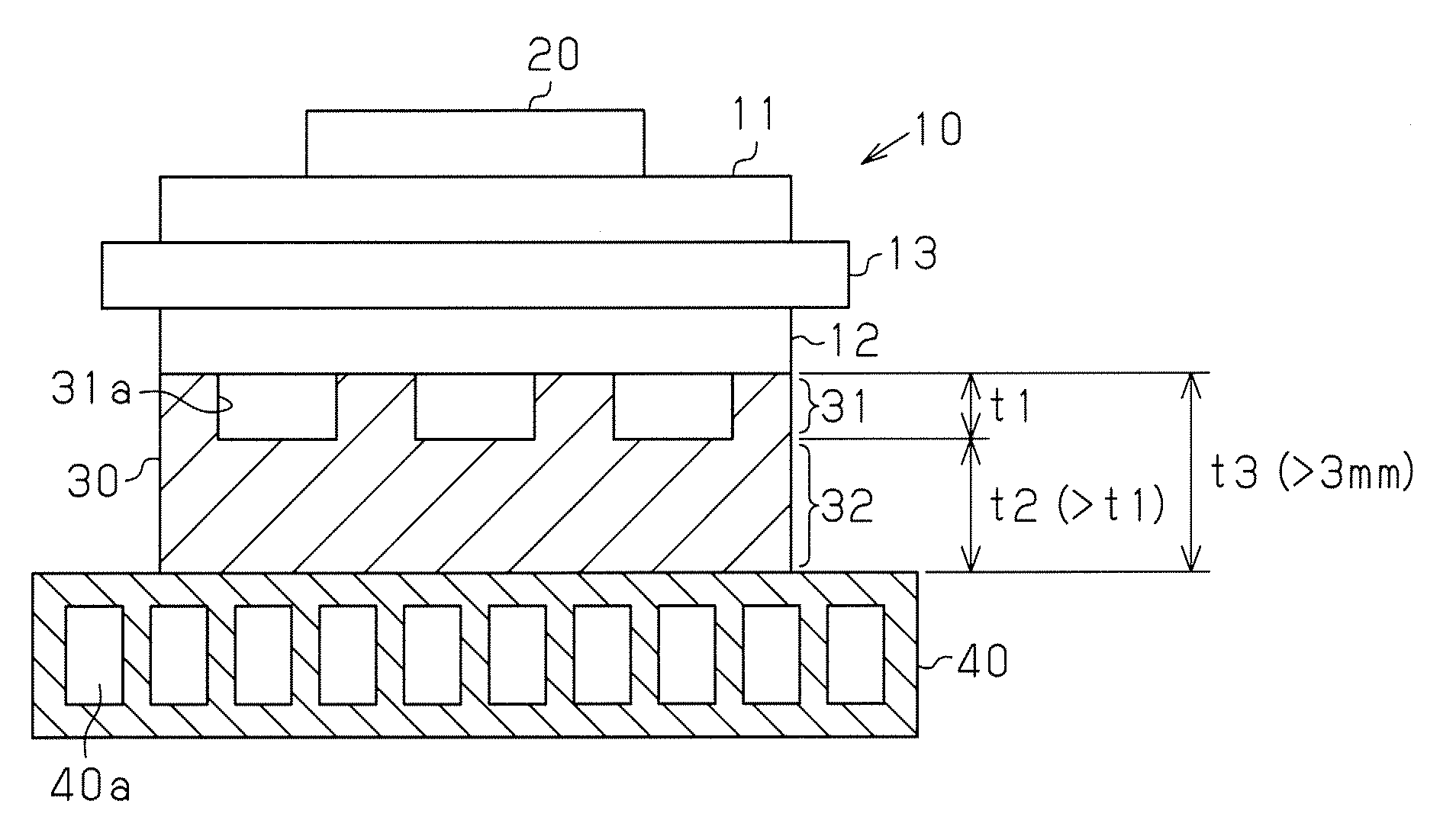
[0016]As shown in FIG. 1, the heat dissipation apparatus includes an insulation substrate 10 and a heat sink 40. The insulation substrate 10 includes a first surface (upper surface), which serves as a heated body receiving surface, and a second surface opposite to the first surface. A heat mass member 30 thermally couples the heat sink 40 and the insulation substrate 10.

[0017]The insulation substrate 10 includes an insulation ceramic substrate 13, a metal circuit layer 11, and a metal layer 12. The metal circuit layer 11 is formed on a first surface (heated body receiving surface) of the ceramic substrate 13. The metal layer 12 is formed from aluminum on a second surface of the ceramic substrate 13. The ceramic substrate 13 is formed from, for...


PUM

PropertyMeasurementUnit
thicknessaaaaaaaaaa
thickness t3aaaaaaaaaa
thicknessaaaaaaaaaa

Abstract

A heat dissipation apparatus including an insulation substrate, a heat sink, and a heat mass member. The insulation substrate includes a first surface serving as a heated body receiving surface and a second surface opposite to the first surface. A heat sink is thermally coupled to the second surface of the insulation substrate. A heat mass member includes a stress reduction portion and a heat mass portion arranged so that one is above the other. The stress reduction portion includes a plurality of recesses in at least either one of a surface facing toward the insulation substrate and a surface facing toward the heat sink of the heat mass member. The heat mass portion has a thickness that is greater than that of the stress reduction portion, and the heat mass member has a thickness that is greater than three millimeters.

Description

BACKGROUND OF THE INVENTION[0001]The present invention relates to a heat dissipation apparatus.[0002]Japanese Laid-Open Patent Publication Nos. 2006-294699 and 2001-148451 each describe an example of a heat dissipation apparatus for a power module that includes a semiconductor device such as an insulated gate bipolar transistor (IGBT).[0003]In Japanese Laid-Open Patent Publication No. 2006-294699, a stress reduction member, which includes a plurality of through holes, is arranged between an insulation substrate and a heat sink. The insulation substrate includes a surface for receiving a heated body. In Japanese Laid-Open Patent Publication No. 2001-148451, a buffer layer is arranged between an insulation substrate and a heat sink. The buffer layer is formed from aluminum silicon carbide (AlSiC), the thermal expansion coefficient of which is between that of the insulation substrate and that of the heat sink.[0004]However, AlSiC is a material that is more expensive than aluminum (Al),...

Claims


Application Information

Patent Timeline
Patent Type & Authority Applications(United States)
IPC IPC(8): H05K7/20
CPCH01L23/3735H01L23/473H01L2924/0002H01L2924/00H01L23/34H05K7/20
Inventor MORI, SHOGOYAMAUCHI, SHINOBUTAMURA, SHINOBU
Owner TOYOTA IND CORP
Learn More