Single integrator sensorless current mode control for a switching power converter

Active Publication Date: 2009-06-11
ANALOG DEVICES INC
View PDF2 Cites 46 Cited by
  • Summary
  • Abstract
  • Description
  • Claims
  • Application Information

AI Technical Summary

Benefits of technology

[0014]A means of providing single integrator sensorless current mode control for a switching power converter is presented. The control method enables high frequency operation with an elegantly simple implementation, which is broadly applicable to a range of switching regulator types and architectures.
[0020]As an SCM controller, the present method does away with true current sensing, thereby eliminating the need for a compensated op amp current sense circuit; instead, the present controller utilizes a fully emulated current signal. This signal may be produced using, for example, a transconductance amplifier connected across the output inductor, or with a resistor connected between the switch node side of the output inductor and the integrating element.
[0022]Because the emulated current sense signal is ‘integrated’, it is essentially noise free, resulting in a signal-to-noise ratio which is typically many times better than that possible with true current mode (TCM) control. And due to the simple nature of the integration compared with true current sensing, operation at frequencies as high as those achieved using voltage mode control is made both possible and practical.
[0023]The present control scheme renders both high and low side current sensing equally trivial. This enables SCM control to easily implement architectures that are impractical with TCM control (e.g., hysteretic ripple current regulator).

Problems solved by technology

Voltage mode is relatively easy to implement, but harder to compensate and typically does not provide as good a transient performance as current mode.
Voltage mode with input voltage feed-forward provides better input line rejection, albeit not as good as current mode, as the instantaneous correction provided by input voltage feed-forward is not an exact equivalent for the integrating nature of an inductor.
Although current mode controllers arguably provide the best overall performance, practical implementations of current mode can be troublesome and performance often falls short of theoretical.
Ironically, the difficulties in implementing current mode typically preclude its use in higher frequency switching regulators.
This results in these higher frequency voltage mode switching regulators ironically having slower transient responses than lower frequency current mode solutions.
For efficiency reasons, the voltage drop across this impedance is often designed to be very low, and hence this voltage signal is subject to significant noise.
Another problem with current mode is settling time.
When a switching converter's power switch is ‘off’, the voltage drop across it is very large.
Inductive and capacitive stray effects can cause significant glitches immediately following this transition.
These factors make current sensing in a switch difficult, due to the settling time needed.
Another issue with current mode control is that it typically requires an increase in the minimum operating voltage.

Method used


Image

  • Single integrator sensorless current mode control for a switching power converter
  • Single integrator sensorless current mode control for a switching power converter
  • Single integrator sensorless current mode control for a switching power converter

Examples


Embodiment Construction

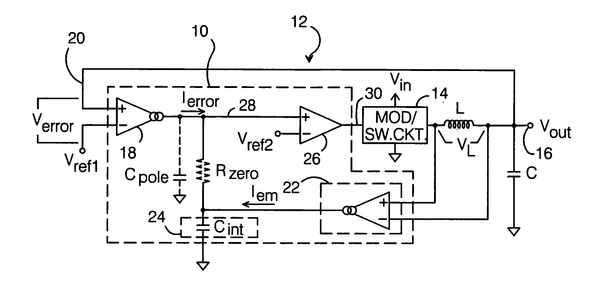
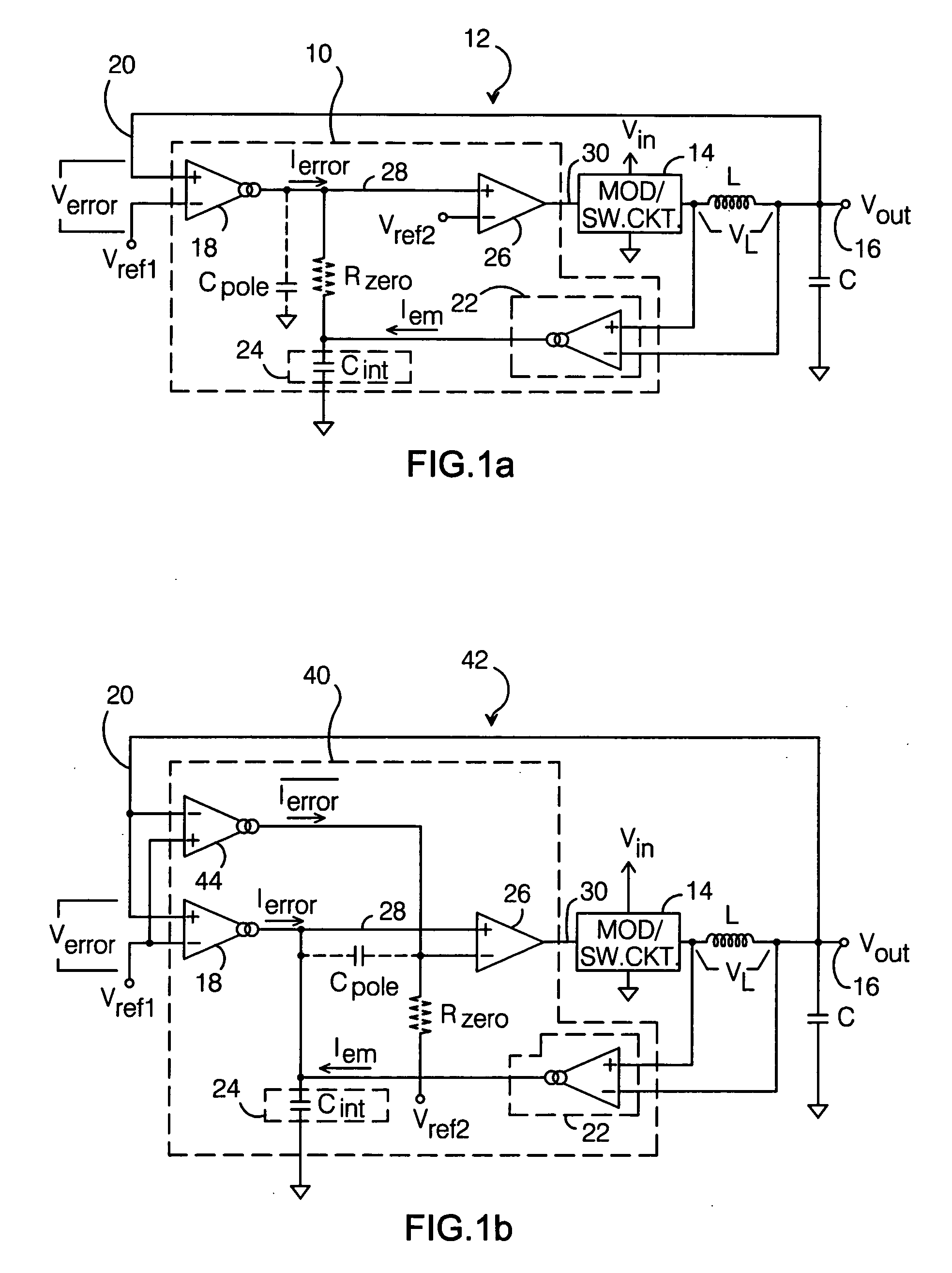
[0035]Before describing the present single integrator SCM controller and control method, a background discussion of current mode operation is presented.

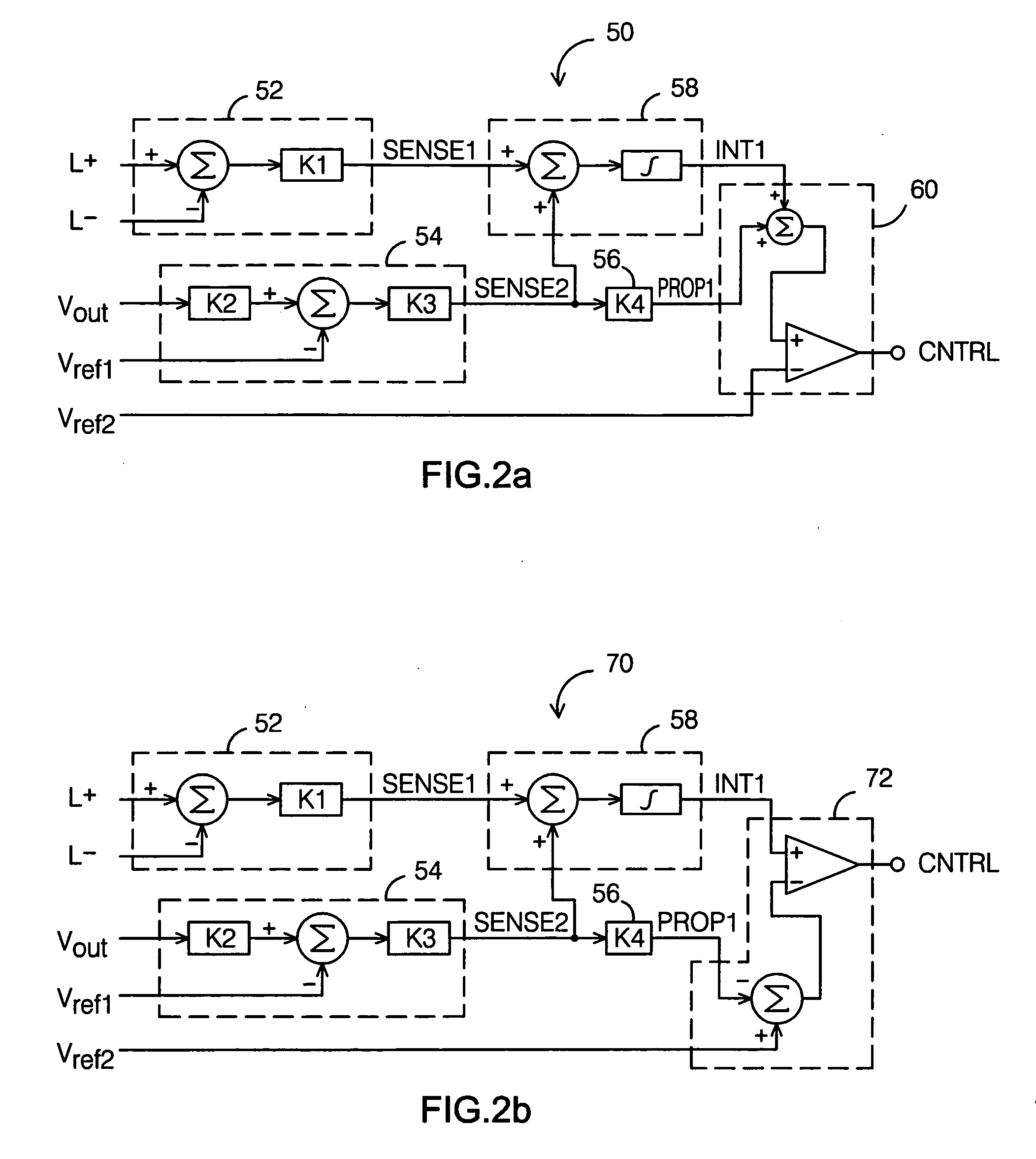
[0036]Current mode control typically requires the use of a current sense amplifier which is used to sense the current in the converter's output inductor. It is generally believed that the offset of the current sense amplifier should be minimized. However, this is only true for a few unique circumstances. For example, for normal “continuous conduction mode” (CCM) operation, the offset of the current sense amplifier is largely irrelevant. The unique circumstances where accurate DC information from the current sense amplifier is needed are:

[0037]1) Zero current: used for sensing the CCM / DCM (discontinuous conduction mode) boundary and providing true diode emulation. Zero current is a unique condition. When measuring the zero value of any given variable, errors in the gain on that variable are irrelevant. However, rather than employ true...


PUM


Abstract

A single integrator sensorless current mode control scheme for a switching power converter requires an amplifier circuit which produces an first current that varies with the difference Verror between a reference voltage and a voltage that varies proportionally with Vout, a circuit which produces a second current that varies with the voltage VL across the output inductor, a single integrating element connected to receive the first and second currents such that it integrates both Verror and VL, and a comparator which receives the integrated output at its first input and a substantially fixed voltage at its second input and produces an output that toggles when the voltage at its first input increases above and falls below the substantially fixed voltage. The comparator output is used to control the operation of the power converter's switching circuit and thereby regulate the output voltage.

Description

RELATED APPLICATIONS[0001]This application claims the benefit of provisional patent application No. 61 / 005,602 to Jonathan Mark Audy, filed Dec. 5, 2007.BACKGROUND OF THE INVENTION[0002]1. Field of the Invention[0003]This invention relates generally to switching power converters, and more particularly, to a sensorless current mode control method for such a converter.[0004]2. Description of the Related Art[0005]Switching power converters require feedback to regulate their output, and as such they typically require frequency compensation in order to guarantee stability. To this end, various switching power converter controller architectures have been developed with different compensation requirements, which provide different levels of performance with respect to stability and transient response.[0006]Three of the most common controller architectures are categorized as follows:[0007]1) Voltage mode[0008]2) Voltage mode with input voltage feed-forward[0009]3) Current mode (with voltage ...

Claims


Application Information

Patent Timeline
IPC IPC(8): G05F1/00
CPCH02M2001/0009H02M3/156H02M1/0009
Inventor AUDY, JONATHAN MARK
Owner ANALOG DEVICES INC
Why Eureka
Try Eureka