
Microphone Circuit

a microphone and circuit technology, applied in the direction of transducer circuits, transducer casings/cabinets/supports, electrostatic transducers, etc., can solve the problems of signal to be amplified, signal is usually small (a few millivolts), signal to be overcome, etc., to reduce the drain to source

Inactive Publication Date: 2009-06-04
VAN KATZ ARTHUR WILLIAM +1
View PDF6 Cites 15 Cited by
  • Summary
  • Abstract
  • Description
  • Claims
  • Application Information

AI Technical Summary

Benefits of technology

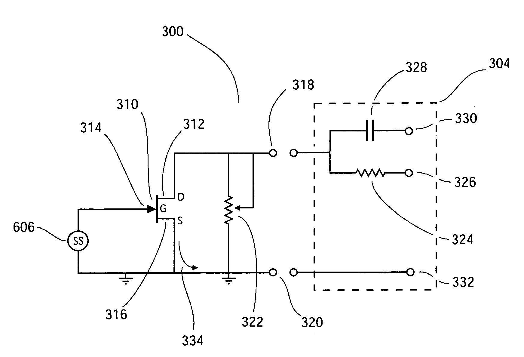
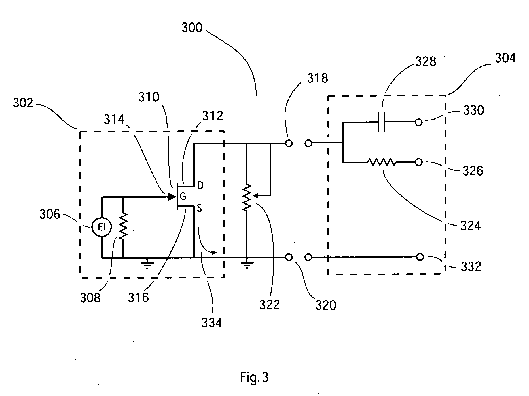
[0021]In one embodiment of the invention, a circuit is provided comprising a signal source having a negative pole bearing a negative charge and a grounded pole connected to ground, a field effect transistor (“FET”) having a drain, a gate and a source, wherein the negative pole of the electret is connected to the gate of the FET, a source of DC electric power is connected to drain of the FET and the source of the FET is connected to ground, the invention comprising a resistor connected between the drain and the source of the FET so as to reduce the drain to source voltage and reduce and linearize the sensitivity of the drain to source voltage in response to changes in the gate to source voltage.

Problems solved by technology

When a microphone is used in open air, there are two challenges to be overcome: the signal is usually small (a few millivolts) and noisy.
The first problem calls for the signal to be amplified before it is suitable for digitizing.
Secondly, the level of noise in the signal may be sufficiently large that speech recognition is either of very poor quality or not possible at all.
However, the mounting of the microphone on the mask means that the microphone can pick up vibrations through its mechanical connection to the shell of the mask.
Unfortunately, little can be done to eliminate humidity.
Papadopoulos points out that “louder speech, breath ‘pops’ and physical jolts can cause large drain current swings”.
In two situations large voltage swings at the gate of the FET within the electret microphone can cause distortion.
Firstly, if swings in the gate voltage cause the gate voltage to become positive, the drain current may become extremely high due to forward conduction through the FET.
Secondly, if the gate voltage becomes large and negative, the drain current may reach cut-off.
In both cases, the signal is clipped and distorted and “speech recognition by computer software is adversely affected”.
Although the signals produced are just intelligible to the human ear, they are not suitable for speech recognition by computer software.
There appear to be four sources causing distortion of the signal:(1) The vibrating membranes within an electret are not designed to handle very loud sounds.
In extreme cases, the membrane may actually strike the surrounding case, causing clipping of the signal or shorting of the signal to zero.
Alternatively, if the gate voltage becomes positive, a very large current flows through the FET, in some circumstances causing damage to the FET itself.
However, with large signals appearing at the gate of the FET, the response is definitely nonlinear.
This causes a distortion of the signal—the “nonlinearity problem”.(4) Large signals produced by an electret microphone can exceed the input limits of down-stream devices such as sound cards or USB adapters—the “large output signal problem”.
Signals exceeding 50 mV are frequently a problem.

Method used


Image

  • Microphone Circuit
  • Microphone Circuit
  • Microphone Circuit

Examples


Embodiment Construction

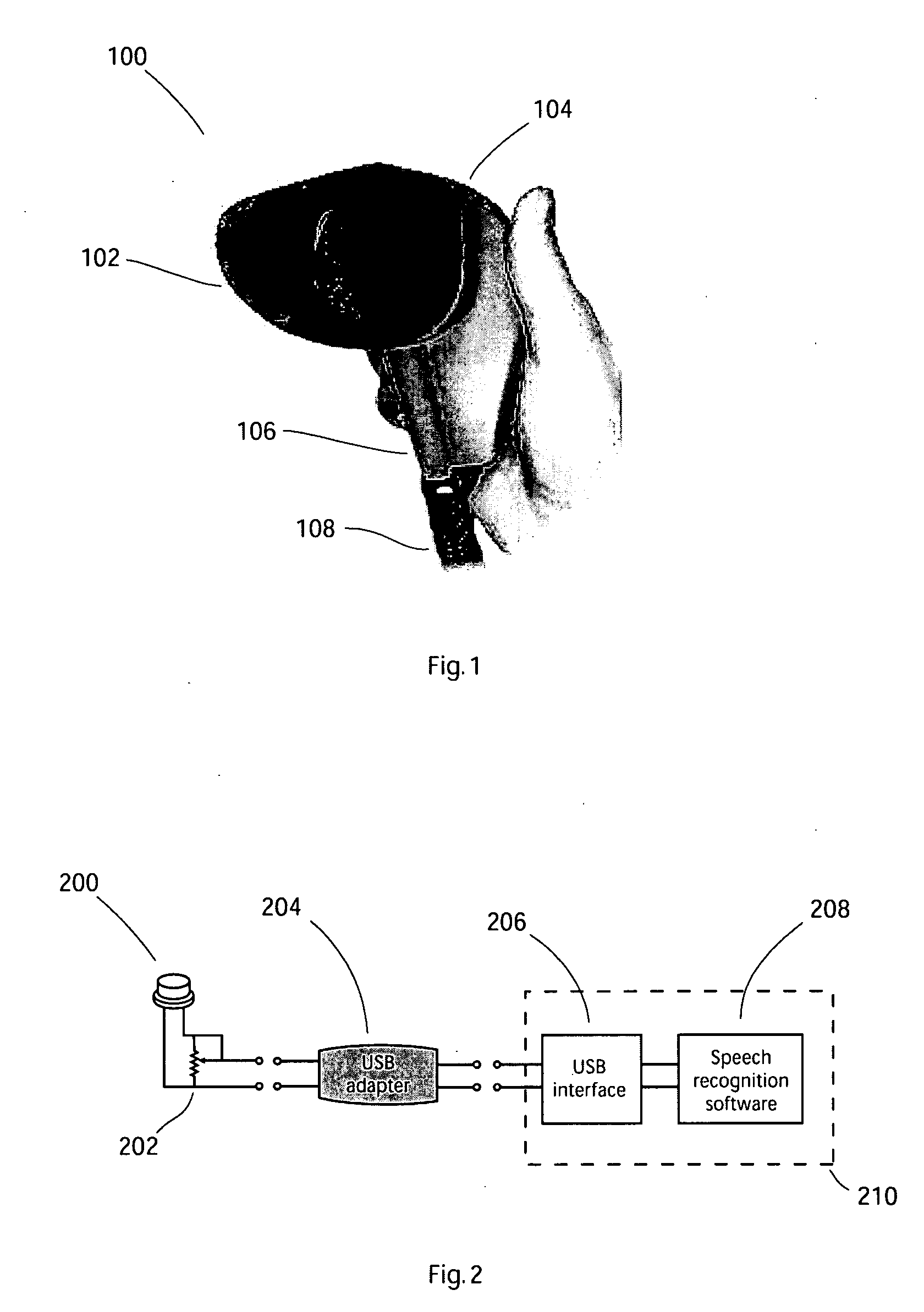
[0031]FIG. 1 is an image showing a general perspective view of a typical mask 100 used for recording speech without disturbing the surrounding environment. 102 shows a mouthpiece covering just the mouth. The mouthpiece 102 is made of a soft elastic rubber-like material to provide comfort and a good acoustic seal around the mouth of the speaker. A hard shell 104 forms the body of the mask and is partially filled with insulating foam. 106 shows a ventilation tube to provide an airflow to assist with speech and the partial removal of moisture. An electrical cable 108 is connected to a microphone (not shown) which is installed within the enclosed space of the mask 100.

[0032]FIG. 2 shows the electrical connections of the components of the preferred embodiment. A two-terminal electret microphone 200 is shown with a potentiometer 202 connected in parallel between the externally accessible drain and source terminals of the FET (not shown) located within the microphone. The electret micropho...


PUM


Abstract

Microphones are used in acoustically insulated masks, headsets, phones and personal digital assistants. Frequently, the microphone provides an input to speech recognition software. The working environment is often humid and the speaker's mouth is in close proximity to the microphone. Frequently the signal suffers from clipping and distortion caused by the large signals and nonlinear response of the microphone circuitry. The claimed invention uses a resistor connected in parallel with the signal source to reduce its sensitivity and to produce a signal suitable for use with speech recognition software. The resistor can be varied for different speakers.

Description

CROSS-REFERENCES TO OTHER APPLICATIONS[0001]This application is a continuation in part of U.S. application Ser. No. 11 / 748,820, filed on May 15, 2007. U.S. application Ser. No. 11 / 748,820 claims the benefit of U.S. provisional application 60 / 820,217, filed Jul. 24, 2006.FIELD OF INVENTION[0002]This invention relates generally to improving the performance of a signal source when loud sounds cause the signal source to generate large signals. Frequently, this occurs when the signal source is placed within a mask, a headset, a phone or a personal digital assistant to record speech for use with speech recognition software.BACKGROUND OF INVENTION[0003]The recognition of speech by software is common. Part of the technology's increased usage is due to the availability of inexpensive hardware for capturing signals generated by microphones. Electret microphones are particularly suitable as they are small (less than 1 cc) and inexpensive (less than $10). Other circuitry (for amplifying, filter...

Claims


Application Information

Patent Timeline
Patent Type & Authority Applications(United States)
IPC IPC(8): H04R3/00
CPCH04R19/016H04R3/00
Inventor VAN KATZ, ARTHUR WILLIAMWEBB, STEPHEN
Owner VAN KATZ ARTHUR WILLIAM
Learn More