
Multilayer, thermally-stabilized substrate structures

a substrate structure and multi-layer technology, applied in the direction of printed circuit manufacturing, printed circuit construction, electrical apparatus construction details, etc., can solve the problems of ensuring thermal stability within the integrated chip, affecting the design of such sips, and increasing the difficulty of maintaining thermal stability

Inactive Publication Date: 2009-06-04
ITT MFG ENTERPRISES LLC
View PDF13 Cites 7 Cited by
  • Summary
  • Abstract
  • Description
  • Claims
  • Application Information

AI Technical Summary

Benefits of technology

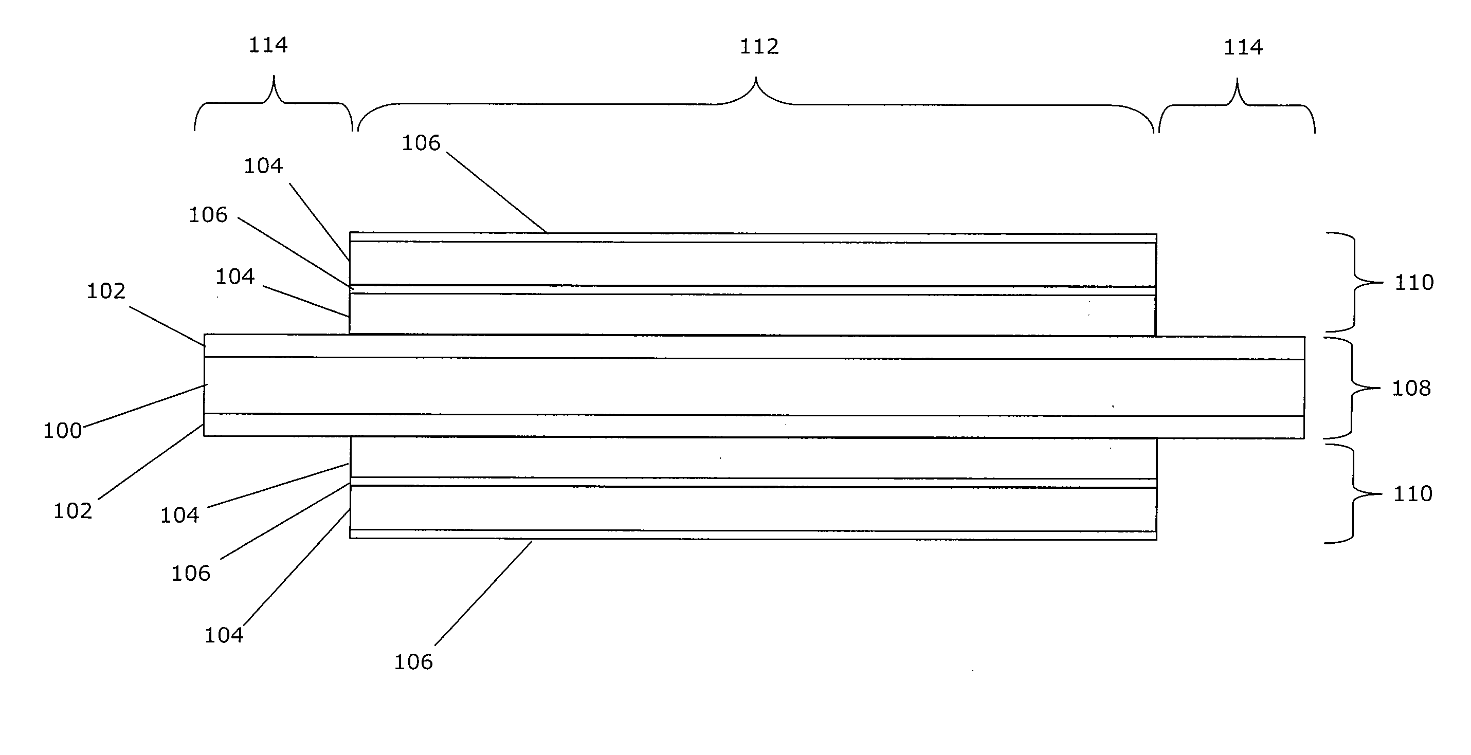
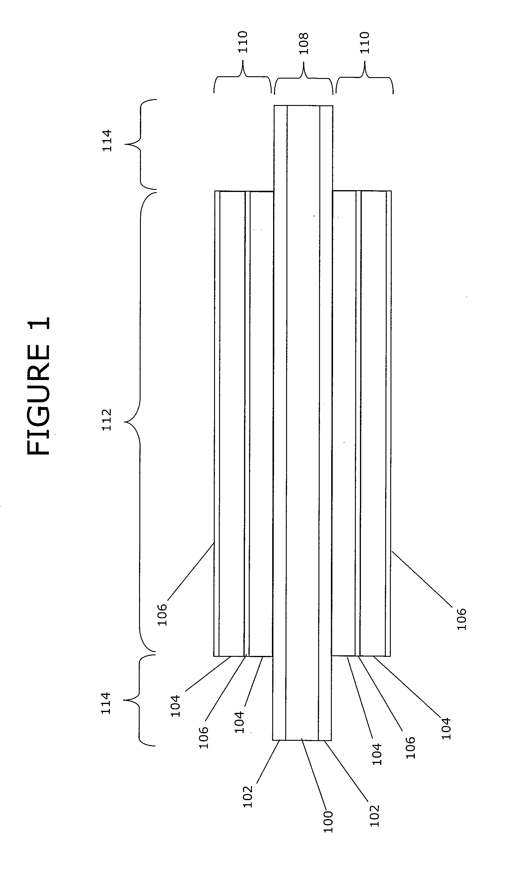
[0008]An exemplary embodiment of the present invention is a multilayer, thermally-stabilized substrate, including: a thermally-conductive core structure, including a central section located horizontally between two edge sections; a top multilayer circuit board connected to the top surface of the central portion of the thermally-conductive core structure; and a bottom multilayer circuit board connected to the bottom surface of the central portion of the thermally-conductive core structure. The thermally-conductive core structure has a core thermal conductance and a effective core horizontal thermal expansion coefficient. The top and bottom multilayer circuit boards each include at least one dielectric layer and at least one electrically-conductive layer, and each have a circuit board thermal conductance that is less than the core thermal conductance of the thermally-conductive core structure. The electrically-conductive layers of the top and the bottom multilayer circuit boards each have a conductive layer horizontal thermal expansion coefficient that is less than or equal to the effective core horizontal thermal expansion coefficient of the thermally-conductive core structure.
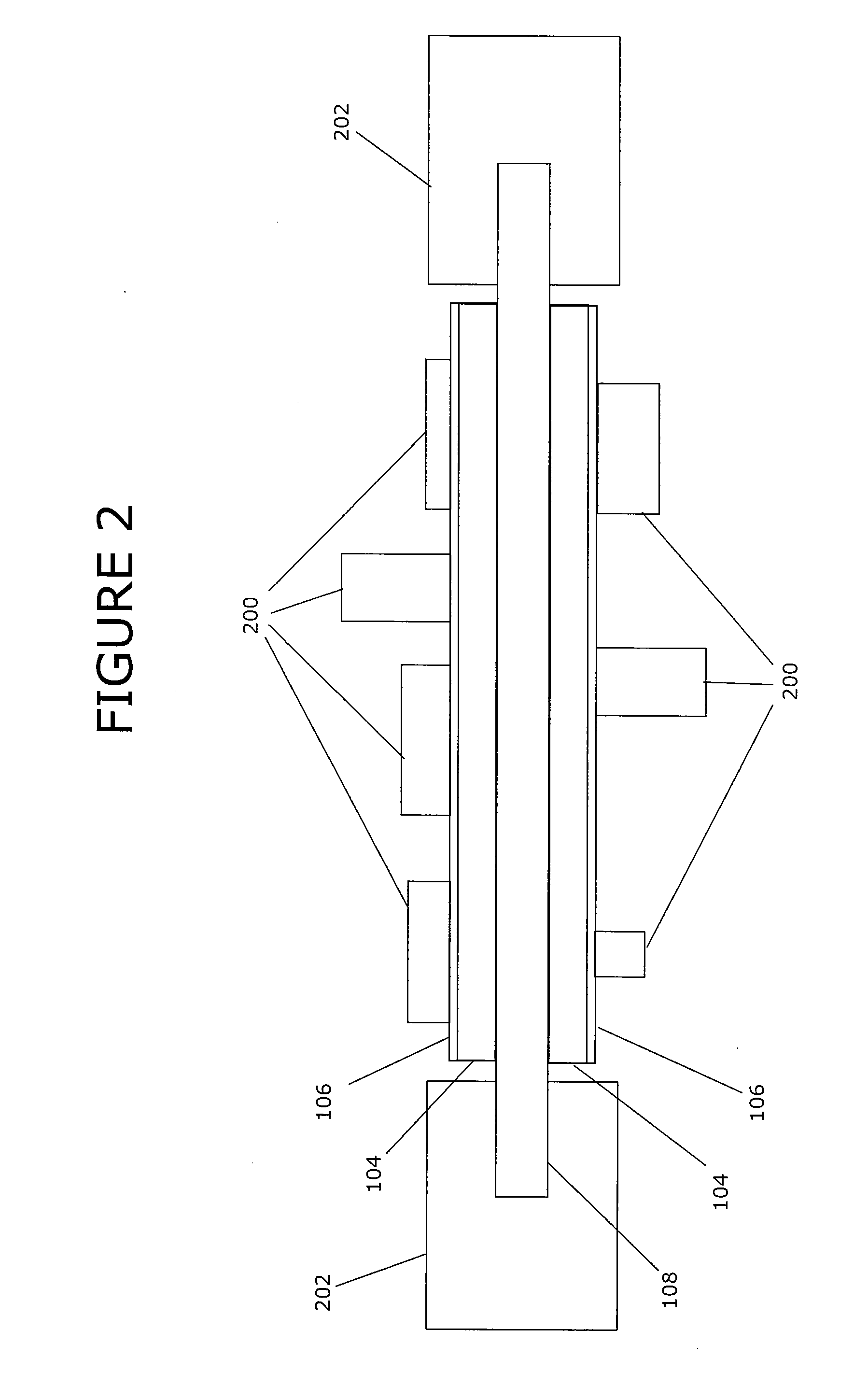
[0009]Another exemplary embodiment of the present invention is a thermally-stabilized system in a package (SIP) including: a multilayer, thermally-stabilized substrate; a plurality of electronic components; and a chip package adapted to hold the multilayer, thermally-stabilized substrate. The multilayer, thermally-stabilized substrate includes: a thermally-conductive core structure, including a central section located horizontally between two edge sections; a top multilayer circuit board connected to the top surface of the central portion of the thermally-conductive core structure; and a bottom multilayer circuit board connected to the bottom surface of the central portion of the thermally-conductive core structure. The thermally-conductive core structure has a core thermal conductance and a effective core horizontal thermal expansion coefficient. The top multilayer circuit board includes at least one dielectric layer and at least one patterned electrically-conductive layer. The bottom multilayer circuit board includes at least one dielectric layer and at least one electrically-conductive layer. The top and bottom multilayer circuit boards each have a circuit board thermal conductance that is less than the core thermal conductance of the thermally-conductive core structure. The electrically-conductive layers of the top and the bottom multilayer circuit boards each have a conductive layer horizontal thermal expansion coefficient that is less than or equal to the effective core horizontal thermal expansion coefficient of the thermally-conductive core structure of the multilayer, thermally-stabilized substrate. The electronic components are mounted on the top multilayer circuit board and electrically coupled to the patterned electrically-conductive layer(s) of the top multilayer circuit board. The chip package includes a heat sink that is thermally coupled to the two edge sections of the thermally-conductive core structure of the multilayer, thermally-stabilized substrate.

Problems solved by technology

One difficulty that designers of such SIPs often face is ensuring thermal stability within these integrated chips.
As both the density of component and the size of SIPs increases, maintaining thermal stability becomes more difficult.
Two related problems that may be caused by excess heat generated by multiple components in densely packed SIPs are elevated operating temperatures and thermal expansion.
Elevated operating temperatures may lead to decreased lifetimes for the electronic components and / or may affect the characteristics of these components during operation.
As the densities of electronic components increase within SIPs this problem is likely to increase.
Increasing the size of SIPs, while maintaining current component densities, may also exacerbate this problem.
Mismatches in thermal expansion coefficients of layers within the substrate and / or the electronic components on the substrate may lead to mechanical stresses.
Temperature cycling may increase the effects of mechanical stresses on an SIP due to thermal expansion mismatches.
These mechanical stresses may lead to damage such as permanent or intermittent breaks in lines of the circuit board and / or in the joints electrically coupling the components to the circuit board.
Because thermal expansion is proportional to size, increasing the size of an SIP increases the thermal expansion mismatch within the structures of the SIP.
In larger, more densely packed SIPs, however, it may be difficult to prevent temperature elevation during operation and the circuit board and electronic components may still encounter significant mechanical stresses due to the resulting temperature cycling.

Method used


Image

  • Multilayer, thermally-stabilized substrate structures
  • Multilayer, thermally-stabilized substrate structures
  • Multilayer, thermally-stabilized substrate structures

Examples


Embodiment Construction

[0014]Exemplary embodiments of the present invention include the use of multilayer substrate structures to improve the thermal stability of systems in a package (SIPs). These exemplary multilayer substrate structures include a core structure that is thermally-conductive and multilayer circuit boards disposed symmetrically above and below the core structure. The core structure and the multilayer circuit boards are configured such that the thermal expansion coefficient in the horizontal plane of the core structure is less than or equal to the thermal expansion coefficient of a respective horizontal plane of the electrically-conductive layers of the multilayer circuit boards.

[0015]The high thermal conductivity of the core structure provides an effective route for heat dissipation during operation, thereby helping to reduce temperature elevation. The formation of the core structure with a relatively low horizontal thermal expansion coefficient helps prevent the insulating layers from ex...


PUM


Abstract

A multilayer, thermally-stabilized substrate, including: a thermally-conductive core structure, including a central section located horizontally between two edge sections; a top multilayer circuit board connected to the top surface of the central portion of the core structure; and a bottom multilayer circuit board connected to the bottom surface of the central portion of the core structure. The core structure has a core thermal conductance and a effective core horizontal thermal expansion coefficient. The top and bottom multilayer circuit boards each include at least one dielectric layer and at least one electrically-conductive layer, and each have a circuit board thermal conductance that is less than the core thermal conductance of the core structure. The electrically-conductive layers of the top and the bottom circuit boards each have a conductive layer horizontal thermal expansion coefficient that is less than or equal to the effective core horizontal thermal expansion coefficient of the core structure.

Description

FIELD OF THE INVENTION[0001]The present invention concerns thermally-stabilized substrate structures having multiple layers. In particular, the present invention allows for the production of thermally-stabilized systems in a package (SIPs).BACKGROUND OF THE INVENTION[0002]The demand for more and more complicated systems in a package (SIPs) that may be formed in a single integrated chip package is driven by a desire for more compact electronic devices, as well as simplifying post-fabrication assembly and packaging of these devices. Simplifying the assembly and packaging of electronic devices may improve durability and quality, as well as decrease the cost of manufacture of these devices.[0003]An SIP typically includes multiple electronic components that are mounted on a multilayer substrate structure having one or more electrically-conductive layer(s) patterned to form circuit boards.[0004]One difficulty that designers of such SIPs often face is ensuring thermal stability within thes...

Claims


Application Information

Patent Timeline
Patent Type & Authority Applications(United States)
IPC IPC(8): H05K7/20
CPCH01L23/3735H01L23/5385H01L2924/0002H05K1/0207H05K1/05H05K1/053H05K1/056H05K1/144H05K3/0061H05K3/3436H05K3/4641H05K2201/0338H05K2201/068H05K2201/0919H01L2924/00
Inventor JUETT, GREGG T.
Owner ITT MFG ENTERPRISES LLC
Learn More