
Device for keeping an inkjet print head clean

a technology for inkjet printing and clean, applied in printing and other directions, can solve the problems of short cleaning path and downtime, inability to use normal operation of the machine, and difficulty in removing contaminants, etc., and achieve optimally high letter throughput, extend the lifespan of the printing device, and increase the functional security of the franking machine

Inactive Publication Date: 2009-06-04
FRANCOTYP POSTALIA
View PDF12 Cites 9 Cited by
  • Summary
  • Abstract
  • Description
  • Claims
  • Application Information

AI Technical Summary

Benefits of technology

[0014]An object of the invention is to expand the functional security of a franking machine to extend the lifespan of the printing device, and to achieve an optimally high letter throughput.
[0015]A more specific object of the invention is to provide a device for cleaning the nozzle exit surface of an inkjet print head in a franking and / or addressing machine with which the entire nozzle exit surface is cleaned in a brief time, contamination of the transport region is avoided, and the technical expenditure is small.

Problems solved by technology

However, the inkjet printing technique has the disadvantage that, in addition to the free spraying of the nozzles, the surface with the nozzle exit openings—called a nozzle surface for short in the following—must be regularly cleaned in order to prevent a choking of the nozzles and to ensure a secure sealing by the sealing cap.
The quick-drying ink in connection with the paper dust leads to contaminations at the typical operating temperature of 40° C. of the inkjet print heads, which contaminations are difficult to remove.
During this time, the machine is not available for the normal operation.
However, the disadvantages outweigh the advantages of short paths and downtimes for the cleaning process.
The transport region is thus contaminated by the rotating impeller in the cleaning process.
This results in an incomplete cleaning of the nozzle surface.
The technical expenditure is considerable.

Method used


Image

  • Device for keeping an inkjet print head clean
  • Device for keeping an inkjet print head clean
  • Device for keeping an inkjet print head clean

Examples


Embodiment Construction

[0026]The representation is schematically executed in part for simplification and for an easier comprehension.

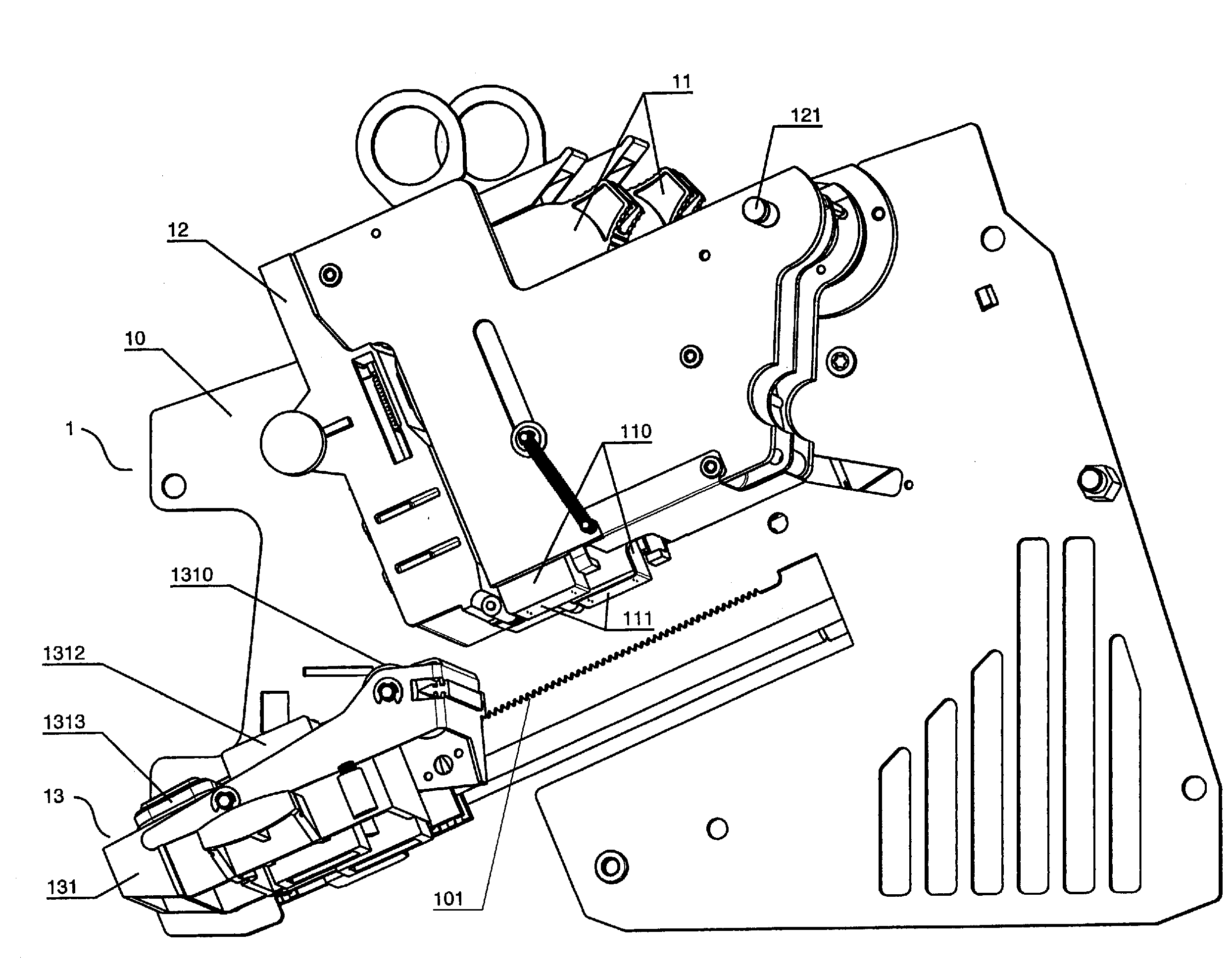
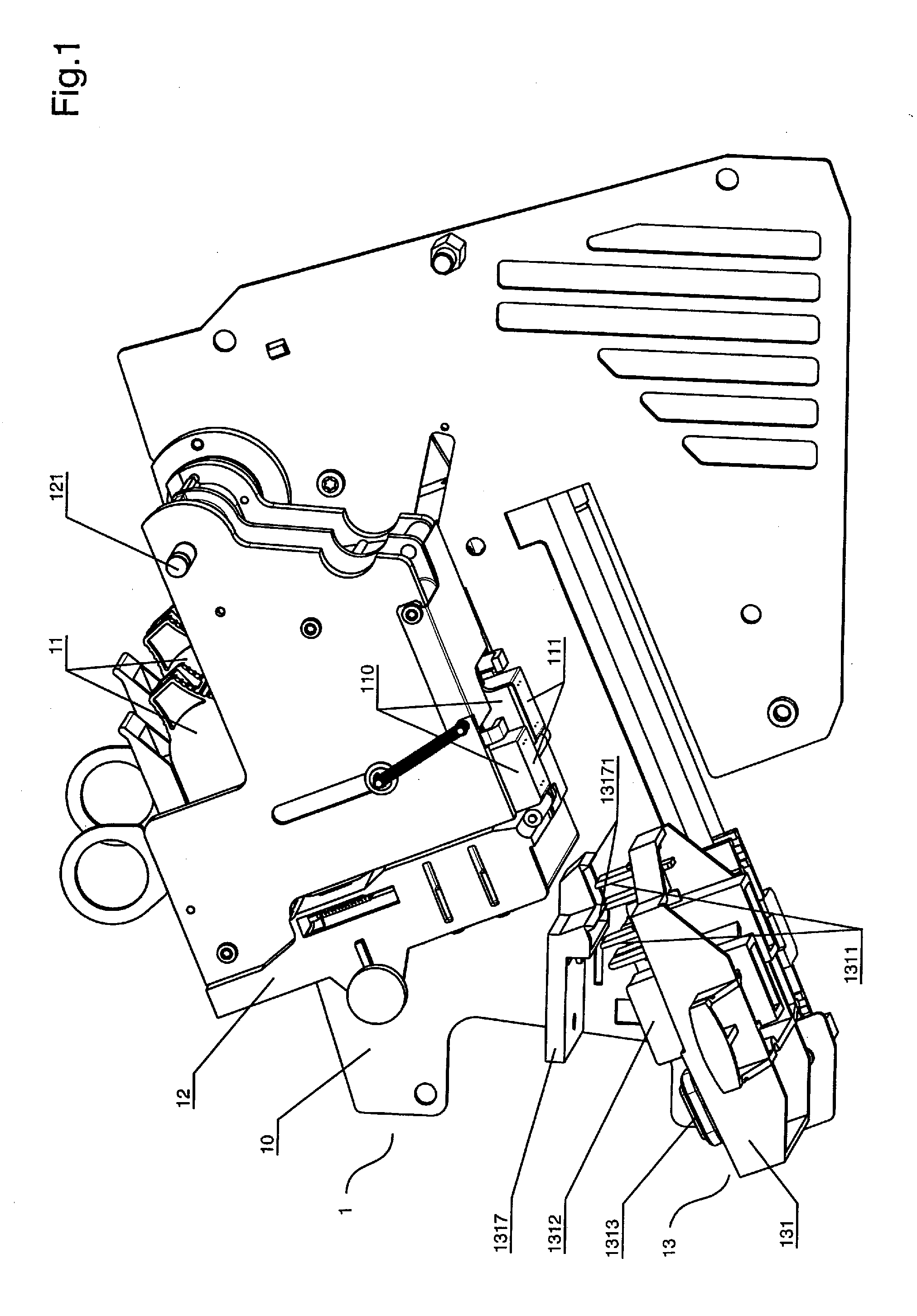
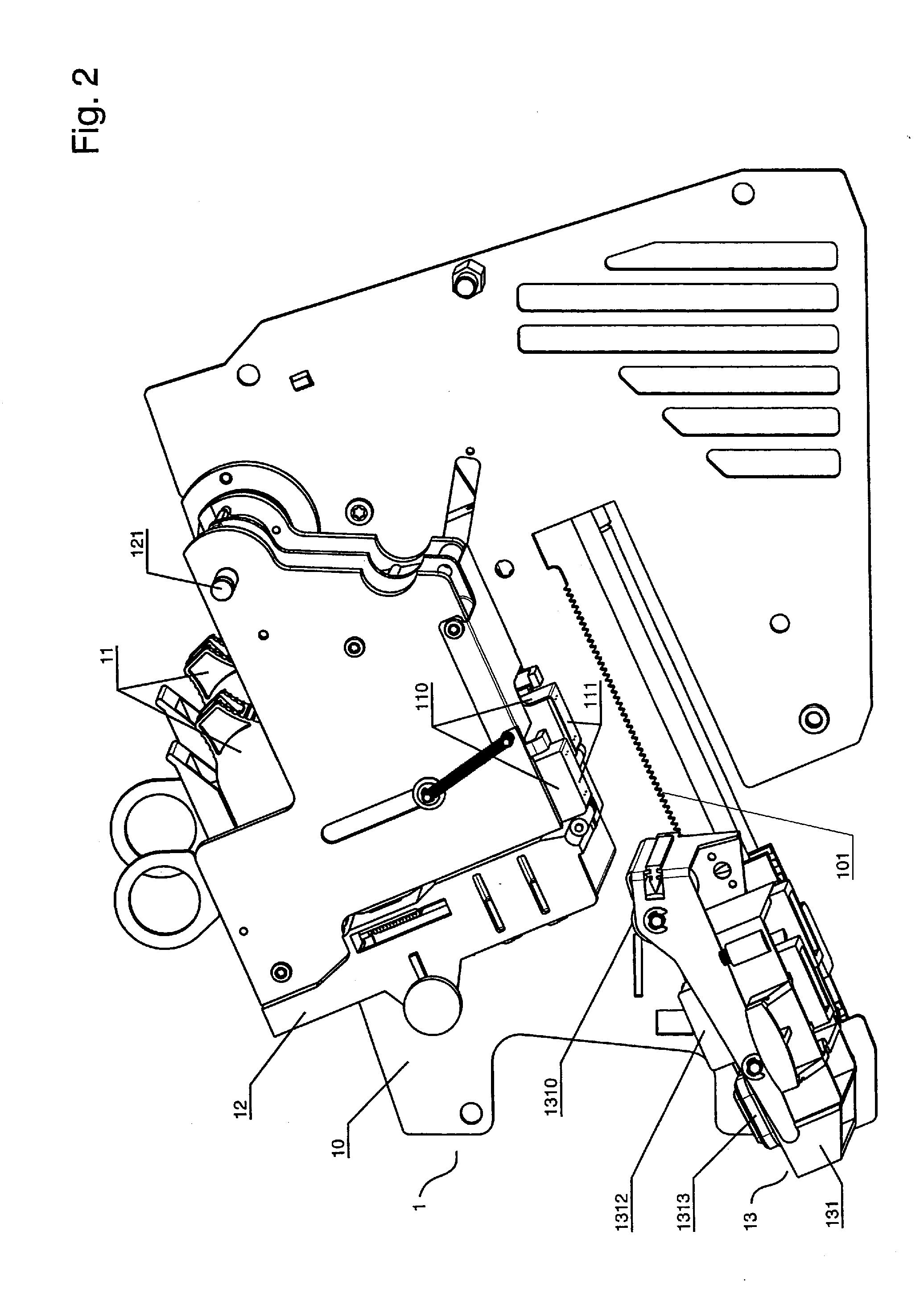
[0027]For the printing system 1 according to FIG. 2, correlation exists with the printing system 1 described above with regard to FIG. 1 except for the features regarding the CSD 13, including the actuator for the wiping roller 1310.

[0028]The printing system 1 has a frame 10; two printing modules 11, a receptacle 12 for both of the aforementioned printing modules, as well as the associated CSD 13 (see also FIG. 3 and FIG. 3A).

[0029]Each printing module 11 has an inkjet print head (IPH in the following) 110 in addition to ink supply and control board (not labeled). The respective nozzle surface 111 of the IPH 110 of the printing modules 11 are arranged offset, parallel to one another. The required print column length is achieved in this manner. The printing modules 11 are correspondingly arranged offset in the receptacle 12.

[0030]The receptacle 12 is supported such that it ca...


PUM


Abstract

In a device for cleaning an inkjet print head (in particular the surface with nozzle exit openings) for a franking and / or addressing machine in which the print substrates are directed along a stationary but pivotably arranged inkjet print head, the entire nozzle exit surface is cleaned in a short time and a contamination of the transport region is avoided, with a small apparatus expenditure, by a wiping device formed by a driven wiping roller that is transversally, non-positively directed along the nozzle exit surface in a cleaning operation, and that continuously, non-positively rests on an associated cleaning element. The nozzle surface is repeatedly wiped off and the wiping roller is simultaneously cleaned in a single pass. An actuator of the wiping roller can be selectively coupled with an actuator for a cleaning and sealing device that operates the cleaning element, or can be autonomous. The cleaning element can be a stripper for the wiping roller that rests parallel to and positively on the wiping roller.

Description

BACKGROUND OF THE INVENTION[0001]1. Field of the Invention[0002]The invention concerns a device for keeping an inkjet print head for franking and / or addressing machines clean, in particular the surface with the nozzle exit openings therein.[0003]2. Description of the Prior Art[0004]It has proven valuable to utilize the advantages of inkjet printing in the field of machine franking and / or addressing. The printing ensues without contact by means of an inkjet print head (see for example DE 44 24 771 C1 and EP 0 696 509 B1). However, the inkjet printing technique has the disadvantage that, in addition to the free spraying of the nozzles, the surface with the nozzle exit openings—called a nozzle surface for short in the following—must be regularly cleaned in order to prevent a choking of the nozzles and to ensure a secure sealing by the sealing cap.[0005]Ink mist and paper dust deposits increasingly occur during the printing operation, and ink deposits increasingly occur during priming. ...

Claims


Application Information

Patent Timeline
Patent Type & Authority Applications(United States)
IPC IPC(8): B41J2/165
CPCB41J2/16585B41J2/16535
Inventor MUHL, WOLFGANGORTMANN, AXEL
Owner FRANCOTYP POSTALIA
Learn More