
Method and Device for Positioning a Movable Part in a Test System

a technology for moving parts and test systems, applied in mechanical control devices, scanning probe microscopy, limiting/preventing/returning movement of parts, etc., can solve the problems of displaceable components moving out of the end, subduing or even completely suppressing, etc., and achieve the effect of accurate fixation of displaceable components in the end position

Inactive Publication Date: 2009-06-04
BRUKER NANO INC +1
View PDF6 Cites 2 Cited by
  • Summary
  • Abstract
  • Description
  • Claims
  • Application Information

AI Technical Summary

Benefits of technology

[0012]The object of the invention is to provide for a method and a device for the positioning of a displaceable component in an examining system where the accuracy of the fixation of the displaceable component in the end position is improved.
[0015]The securing of the resting status of the displaceable component in the end position in the proposed mode enables the maintaining of the positioning of the displaceable component in the end position with high precision. Such a level of precision is, for example, desirable in conjunction with various experimental examinations. For example, in this way an improved force-spacing-spectroscopy is made possible because disturbing movements of the displaceable component are prevented.
[0036]It can be envisaged that a device for the positioning of a displaceable component in one of the previously described types is arranged itself on a further displaceable component which then, on its part, is displaced according to the above-mentioned types relative to a fixed-positioned component. Such an arrangement originates, for example, when two x-y-z scanning devices, known also as scanners, are combined with one another. In this way, for example, faster scanning movements can be performed even if only smaller scanning ranges can be covered. Subsequently, positioning devices can be combined with one another wherein a positioning device takes over a rough setting and a further positioning device combined with this then takes over the precision setting. Both positioning devices, for themselves as such, are configured according to one of the previously described model types.

Problems solved by technology

Disturbing influences on the displaceable component in the end position which can lead to a situation where the displaceable component moves out of the end position in an undesirable manner, are subdued or even completely suppressed.

Method used


Image

  • Method and Device for Positioning a Movable Part in a Test System
  • Method and Device for Positioning a Movable Part in a Test System
  • Method and Device for Positioning a Movable Part in a Test System

Examples


Embodiment Construction

OF THE INVENTION

[0037]The invention is described as follows in greater detail on the basis of embodiment examples with reference to the Figures of a drawing. These Figures show the following:

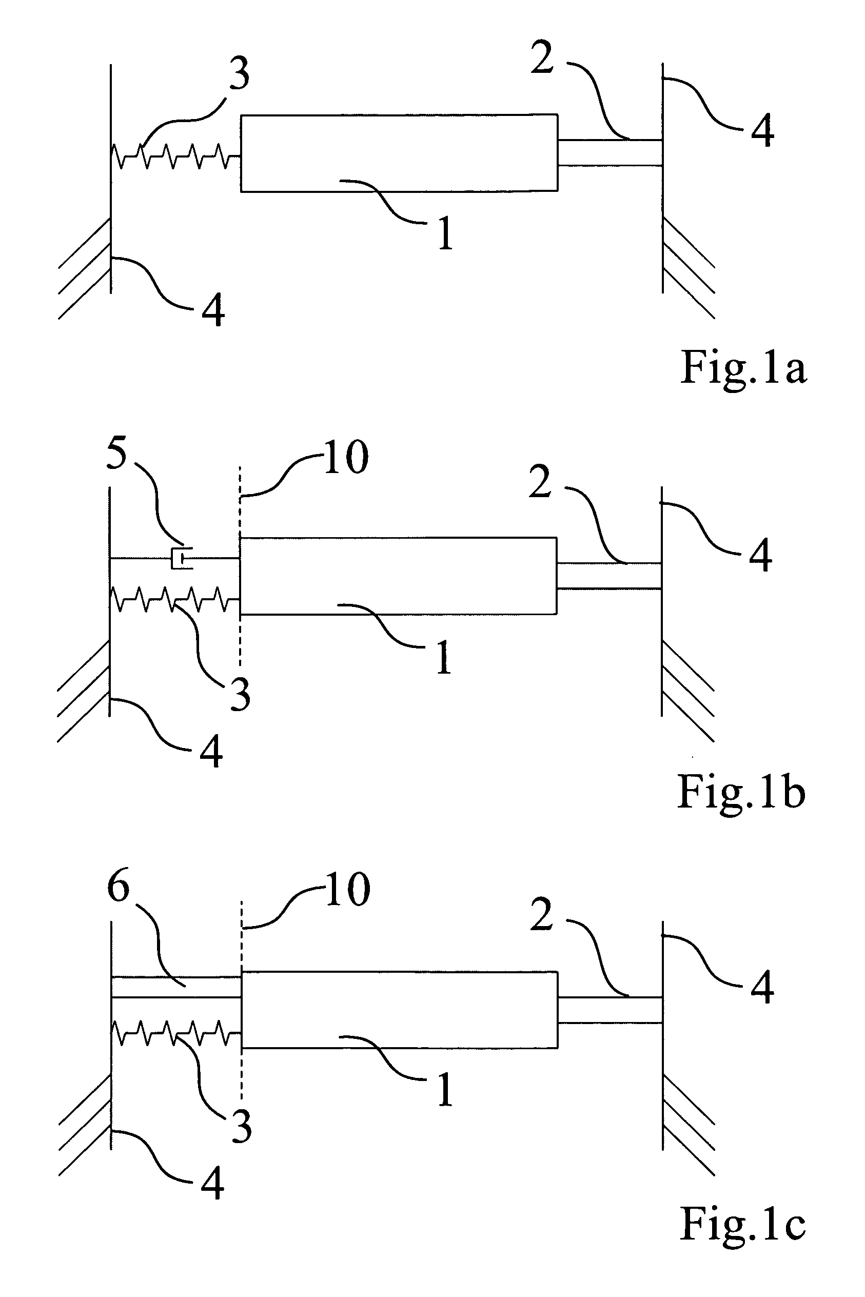
[0038]FIG. 1a to 1c a schematic illustration of an arrangement with a frame and, relative thereto, a displaceable component in one embodiment;

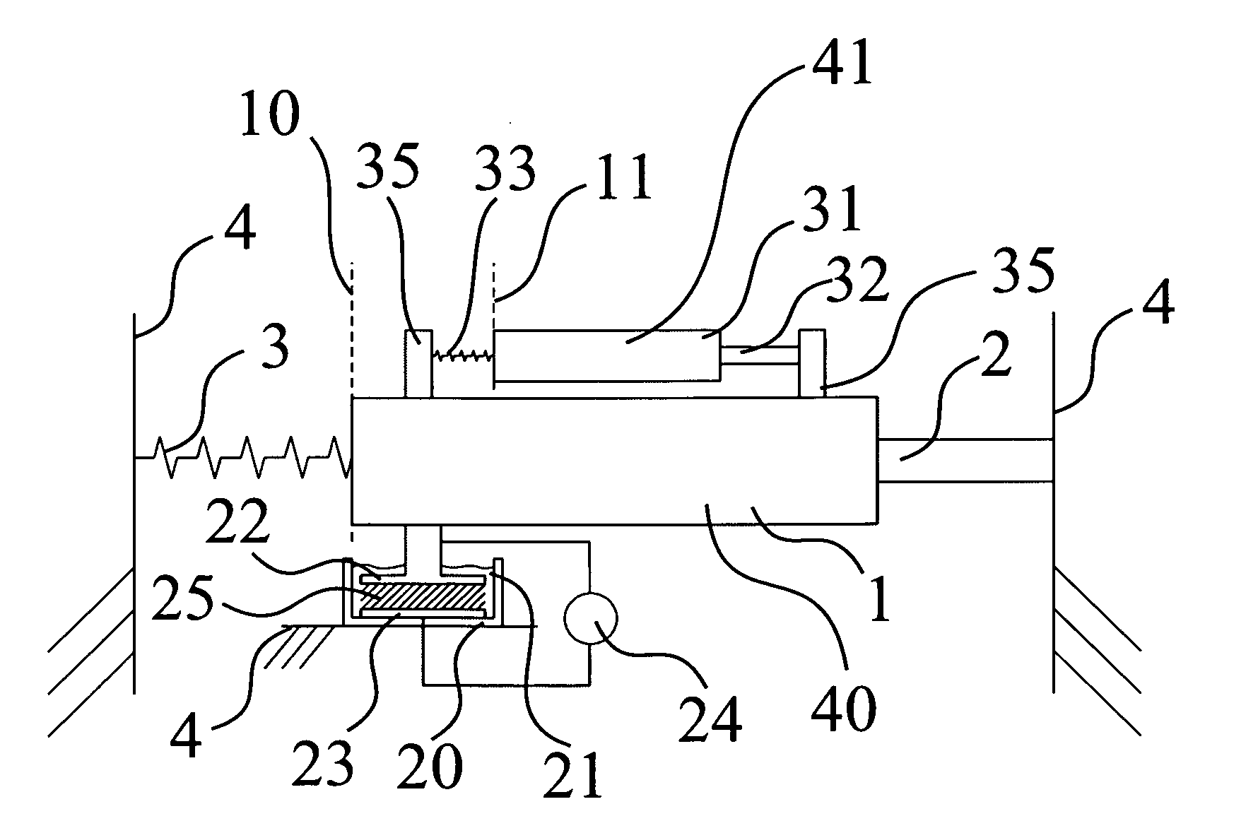
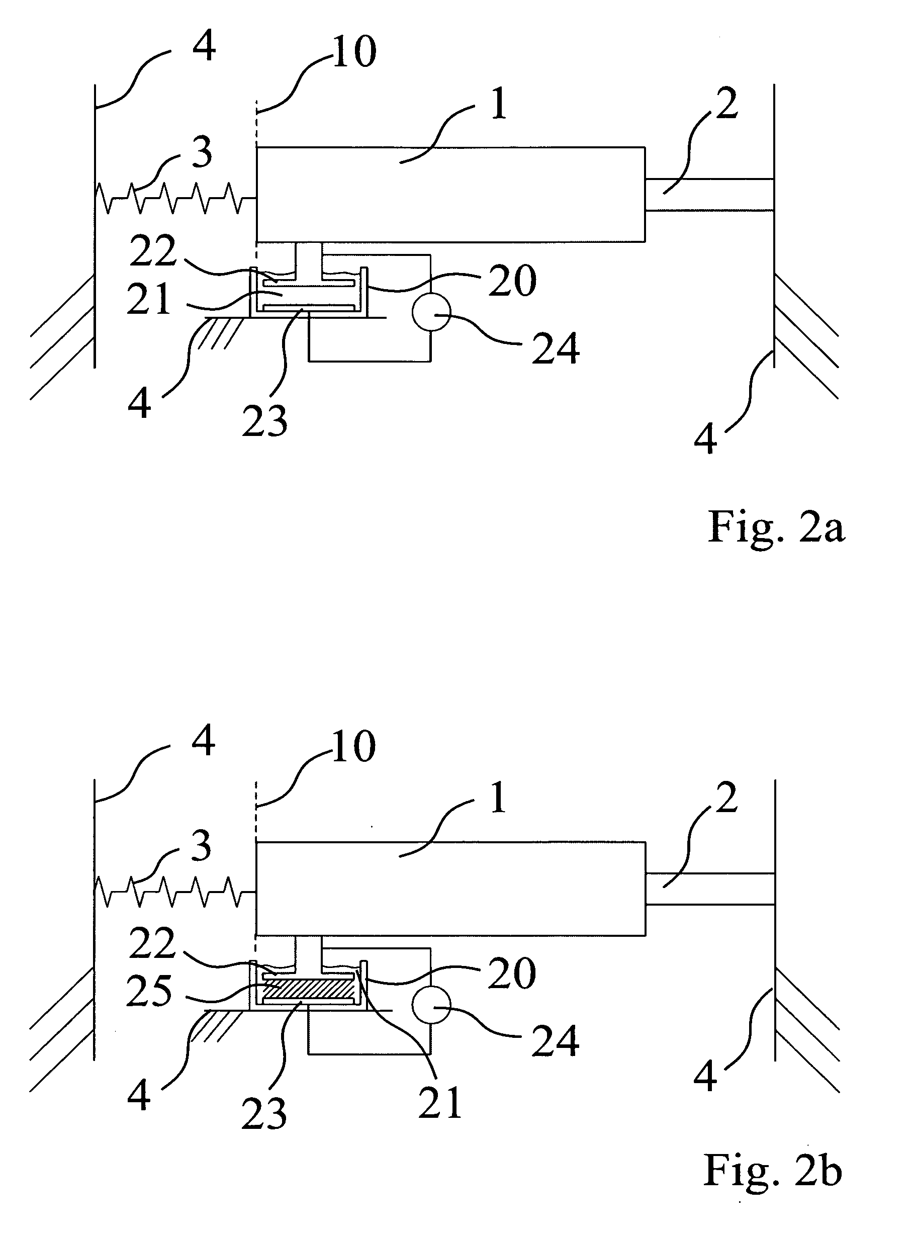
[0039]FIGS. 2a and 2b a schematic illustration of an arrangement with a frame and, relative thereto, a displaceable component in a further embodiment; and

[0040]FIG. 3 a schematic illustration of an arrangement with a frame and, relative thereto, a displaceable component on which a further positioning device is formed.

[0041]FIGS. 1a to 1b show a schematic illustration of an arrangement with a frame and, relative thereto, a displaceable component in one embodiment.

[0042]According to FIG. 1a, a displaceable component 1 is connected to a stationary formed frame 4 by way of an actuating element 2 and a spring 3. The spring 3 can also be omitted in another embod...


PUM


Abstract

The invention relates to a method and a device for the positioning of a displaceable component in an examining system, particularly a measuring or an analytic system wherein, during the process, the displaceable component is displaced with the support of an actuating element coupled to the displaceable component from a home position into an end position, wherein the actuating element is moved by means of a drive force and the displaceable component is impacted with a fixation force fixating the displaceable component in the end position by way of a fixation component connected to the displaceable component, where the fixation component is submerged at least partially in a reservoir of a medium and is fixated in the medium by means of the transformation of the medium from a liquid state into a solidified state, wherein the medium is transformed from the liquid state into the solidified state by means of the impact-application with a manipulating variable.

Description

[0001]The invention relates to a method and a device for the positioning of a displaceable component in an examining system, particularly a measuring or an analytic system.BACKGROUND OF THE INVENTION[0002]The positioning of components is normally performed with the support of a setting element which serves the purpose of establishing a movement of a displaceable component opposite another component which, on its part, remains in the rest position during the displacement. In an examining system, the non-moved component during the displacement of the displaceable component can also be regarded as being a type of frame. For this reason, this designation is also adopted in the following.[0003]The examining system in the sense of this application is a plant, an apparatus or a device that is suitable for performing research or analysis on any examination object with regard to at least one characteristic of a physical, chemical or biological nature. Such systems are frequently allocated to...

Claims


Application Information

Patent Timeline
Patent Type & Authority Applications(United States)
IPC IPC(8): G05G5/14G05G5/04G01Q10/04G01Q70/04
CPCB82Y35/00G01N35/04G01Q70/04G01Q10/04G01N2035/0491
Inventor KNEBEL, DETLEFJAHNKE, TORSTEN
Owner BRUKER NANO INC
Learn More