Cooling System, Control Method of Cooling System, and Vehicle Equipped With Cooling System

a technology of cooling system and control method, which is applied in the direction of hybrid vehicles, process and machine control, instruments, etc., can solve the problems of excessive cooling of engine and motor, excessive cooling of motor, excessive cooling of engine, etc., and achieve the effect of reducing power consumption

Inactive Publication Date: 2009-06-04
TOYOTA JIDOSHA KK
View PDF18 Cites 34 Cited by
  • Summary
  • Abstract
  • Description
  • Claims
  • Application Information

AI Technical Summary

Benefits of technology

[0004]In the cooling system, the control method of the cooling system, and the vehicle equipped with the cooling system, there would thus be a demand for adequately cooling down a drive train having multiple drive systems respectively including heat-generating drive sources. In the cooling system, the control method of the cooling system, and the vehicle equipped with the cooling system, there would also be a demand for reducing the power consumption of an electric pump configured to pressure-feed a cooling medium to cool down the drive train.
[0007]The cooling system according to one aspect of the invention sets the first flow rate demand required for cooling down the first drive system based on the temperature of the cooling medium and the driving state of the first drive system, while setting the second flow rate demand required for cooling down the second drive system based on the temperature of the cooling medium and the driving state of the second drive system. The flow rate distribution regulator and the electric pressure feeder are then controlled to make the flow rate of the cooling medium flowed into the first drive system and the flow rate of the cooling medium flowed into the second drive system respectively equal to the set first flow rate demand and the set second flow rate demand. The flow of the cooling medium into the first drive system at the first flow rate demand required for cooling down the first drive system and the flow of the cooling medium into the second drive system at the second flow rate demand required for cooling down the second drive system enable both the first drive system and the second drive system to be adequately cooled down. Controlling the electric pressure feeder to make the flow of the cooling medium into the first drive system at the first flow rate demand required for cooling down the first drive system and the flow of the cooling medium into the second drive system at the second flow rate demand required for cooling down the second drive system desirably reduces the power consumption of the electric pressure feeder, compared with the conventional cooling system of pressure feeding the cooling medium into the first drive system and the second drive system at excessively high flow rates exceeding the required flow rates for cooling down.
[0008]In one preferable application of the cooling system according to the above aspect of the invention, the first drive system includes an internal combustion engine as the first drive source. The second drive system includes a motor as the second drive source and a driving circuit for driving the motor. The first state detector detects a rotation speed and a torque of the internal combustion engine as the driving state of the first drive system. The second state detector detects a value of electric current flowing through the driving circuit as the driving state of the second drive system. The cooling system of this application enables all the internal combustion engine, the motor, and the driving circuit for the motor to be adequately cooled down.
[0009]In one preferable embodiment of the cooling system according to the above aspect of the invention, the cooling medium temperature detector is located in an upstream of the first drive system on the circulation flow path. The cooling system of this embodiment further has: a radiator configured to cool down the cooling medium by heat exchange with outside air; a bypass passage branched off from the circulation flow path and arranged to bypass the radiator and thereby flow the cooling medium from a downstream of the first drive system to an upstream of the cooling medium temperature detector; and a switchover mechanism provided at a junction of the circulation flow path and the bypass passage and configured to switch over a flow passage of the cooling medium to flow the cooling medium through the radiator when a temperature of the cooling medium flowing through the junction is not lower than a preset level and to flow the cooling medium with bypassing the radiator when the temperature of the cooling medium flowing through the junction is lower than the preset level. At the temperature of the cooling medium flowing through the junction of the circulation flow path and the bypass passage that is lower than the preset level, the cooling medium is flowed with bypassing the radiator. Such flow control effectively lowers the cooling efficiency of the cooling medium and thereby prevents the first drive system and the second drive system from being excessively cooled down. At the temperature of the cooling medium flowing through the junction of the circulation flow path and the bypass passage that is equal to or higher than the preset level, on the other hand, the cooling medium is flowed through the radiator. Such flow control accelerates heat radiation of the cooling medium by means of the radiator, so as to lower the flow rates of the cooling medium flowed into the first drive system and into the second drive system and thus desirably reduce the power consumption of the electric pressure feeder.
[0011]The vehicle according to this aspect of the invention is equipped with the cooling system having any of the above configurations and accordingly has the similar effects and advantages to those of the cooling system according to the invention described above. Namely the vehicle of this aspect enables both the first drive system and the second drive system to be adequately cooled down and desirably reduces the power consumption of the electric pressure feeder.
[0013]The control method of the cooling system according to another aspect of the invention sets the first flow rate demand required for cooling down the first drive system based on the temperature of the cooling medium and the driving state of the first drive system, while setting the second flow rate demand required for cooling down the second drive system based on the temperature of the cooling medium and the driving state of the second drive system. The flow rate distribution regulator and the electric pressure feeder are then controlled to make the flow rate of the cooling medium flowed into the first drive system and the flow rate of the cooling medium flowed into the second drive system respectively equal to the set first flow rate demand and the set second flow rate demand. The flow of the cooling medium into the first drive system at the first flow rate demand required for cooling down the first drive system and the flow of the cooling medium into the second drive system at the second flow rate demand required for cooling down the second drive system enable both the first drive system and the second drive system to be adequately cooled down. Controlling the electric pressure feeder to make the flow of the cooling medium into the first drive system at the first flow rate demand required for cooling down the first drive system and the flow of the cooling medium into the second drive system at the second flow rate demand required for cooling down the second drive system desirably reduces the power consumption of the electric pressure feeder, compared with the conventional cooling system of pressure feeding the cooling medium into the first drive system and the second drive system at excessively high flow rates exceeding the required flow rates for cooling down.

Problems solved by technology

The above prior art cooling system, however, fails to adequately cool down the engine and the motor in some operating conditions of the engine and the motor.
This flow rate control, however, simultaneously increases the flow rate of the coolant flowed into the motor and may cause the motor to be excessively cooled down.
This flow rate control, however, simultaneously increases the flow rate of the coolant flowed into the engine and may cause the engine to be excessively cooled down.
In these operating conditions of the engine and the motor, it is difficult to adequately cool down both the engine and the motor.
The increased flow rate of the coolant flowed into either the engine or the motor increases the overall flow rate of the coolant and thus undesirably increases the power consumption of the electric pump.

Method used


Image

  • Cooling System, Control Method of Cooling System, and Vehicle Equipped With Cooling System
  • Cooling System, Control Method of Cooling System, and Vehicle Equipped With Cooling System
  • Cooling System, Control Method of Cooling System, and Vehicle Equipped With Cooling System

Examples


Embodiment Construction

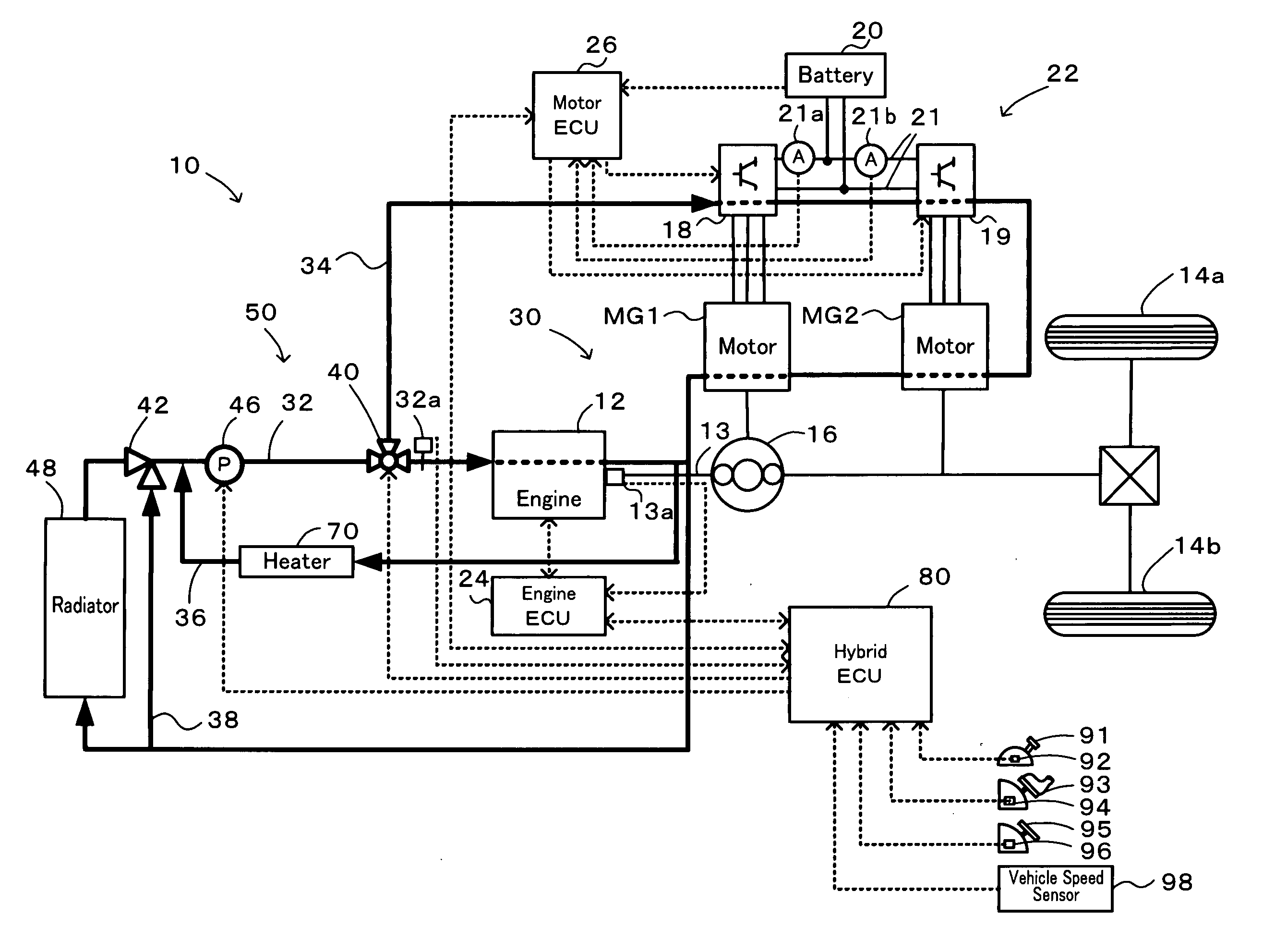
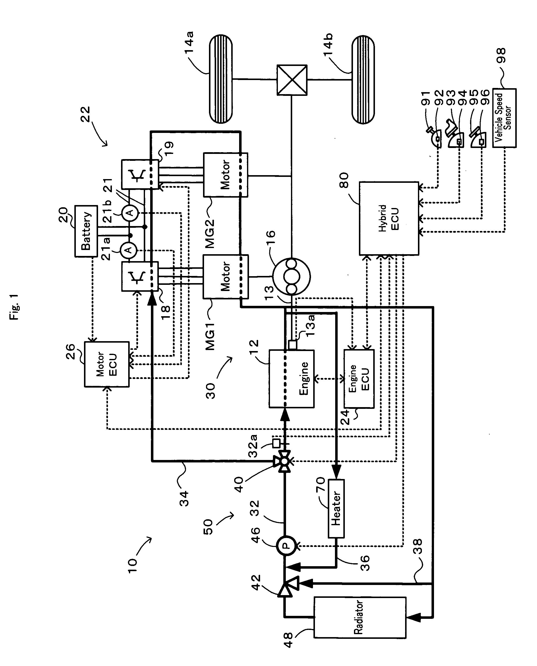
[0019]One mode of carrying out the invention is described below as a preferred embodiment with reference to the accompanied drawings. FIG. 1 schematically illustrates the configuration of a hybrid vehicle 10 equipped with a cooling system 50 in one embodiment according to the invention. The hybrid vehicle 10 of the embodiment is equipped with a drive train 30 and a hybrid electronic control unit (hereafter referred to as hybrid ECU) 80 configured to control the operations of the whole hybrid vehicle 10, as well as the cooling system 50. The drive train 30 includes an engine 12, a planetary gear mechanism 16 designed to have a carrier connected to a crankshaft 13 of the engine 12 and a ring gear connected to a driveshaft linked with an axle of front wheels 14a and 14b, a motor MG1 configured to have a rotating shaft connected to a sun gear of the planetary gear mechanism 16 and to have power generation capability, a motor MG2 configured to have a rotating shaft connected to the ring ...


PUM


Abstract

A cooling system is equipped with a circulation flow path arranged to flow a coolant into an engine, a motor drive system flow path branched off from the circulation flow path and arranged to flow the coolant into a motor drive system, a flow rate distribution regulator provided at a junction of the circulation flow path and the motor drive system flow path, and an electric pump configured to pressure-feed the coolant through the circulation flow path. In the cooling system, the procedure of flow rate control sets an engine flow rate demand Vwe based on a rotation speed Ne and a torque te of the engine and a coolant temperature Te (step S110), while setting a motor flow rate demand Vwm based on an inverter current Iinv of the motor drive system and the coolant temperature Te (step S120). The flow rate distribution regulator and the electric pump are then controlled to make a flow rate of the coolant flowed into the engine and a flow rate of the coolant flowed into motors and inverters included in the motor drive system respectively equal to the set engine flow rate demand Vwe and the set motor flow rate demand Vwm (steps S130 and S140).

Description

TECHNICAL FIELD[0001]The present invention relates to a cooling system, a control method of the cooling system, and a vehicle equipped with the cooling system.BACKGROUND ART[0002]One proposed structure of a cooling system includes a circulation flow path arranged to circulate a coolant for cooling down an engine, a branch flow path branched off from the circulation flow path and arranged to flow the coolant into a motor and an inverter, and an electric pump configured to pressure-feed the coolant through the circulation flow path (see, for example, Patent Document 1). In this proposed structure of the cooling system, the electric pump is controlled to increase the flow rate of the coolant with an increase in temperature of the coolant flowed through the engine and with an increase in temperature of the coolant flowed through the motor, for the purpose of adequately cooling down the engine and the motor.Patent Document 1: Japanese Patent Laid-Open No. 2002-227644DISCLOSURE OF THE INV...

Claims


Application Information

Patent Timeline
IPC IPC(8): B60H3/00G05D23/00F01P5/10F01P7/16
CPCB60K1/02Y02T10/6239B60K6/445B60K11/02B60K2001/003B60L2240/441B60L2240/443B60L2240/445B60W10/30B60W20/00B60W2510/0638B60W2510/0657B60W2510/0676B60W2520/10B60W2540/10B60W2540/12F01P5/12F01P7/164F01P2005/125F01P2025/62F01P2025/64F01P2050/24B60K6/365Y02T10/62B60W10/06F01P5/10B60K6/20F01P7/16
Inventor SUZUKI, TAKASHI
Owner TOYOTA JIDOSHA KK
Why Eureka
Try Eureka