
Ophthalmic laser treatment device

a laser treatment and ophthalmic technology, applied in the field of ophthalmic laser treatment devices, can solve the problems of reducing the intensity of the laser, which defies the draw of the necessary therapeutical, and achieves the effect of high precision and good respons

Inactive Publication Date: 2009-05-28
KATAOKA TAKUYA
View PDF6 Cites 90 Cited by
  • Summary
  • Abstract
  • Description
  • Claims
  • Application Information

AI Technical Summary

Benefits of technology

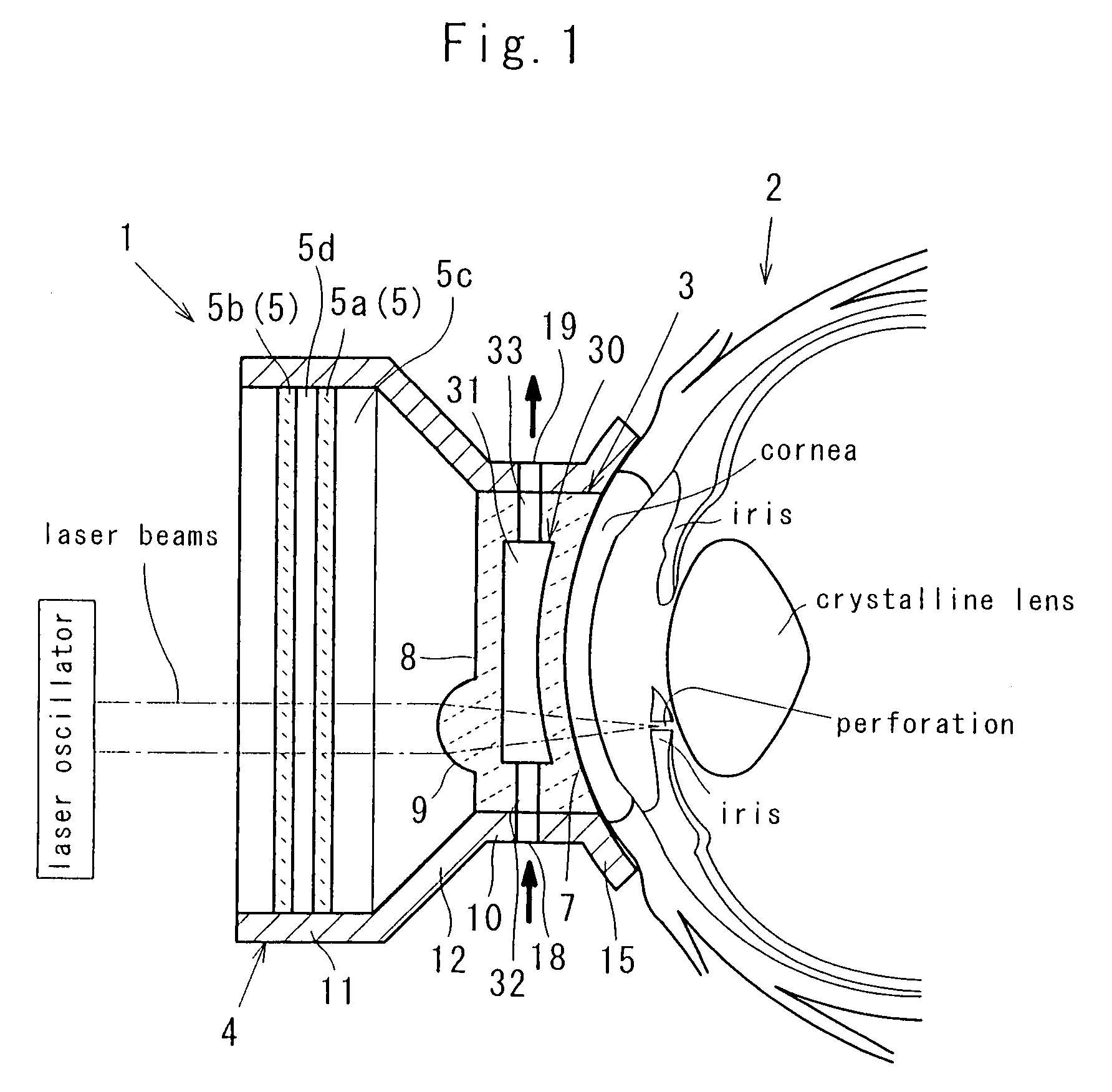
[0022]This enables the operator to form the fluid passage between the light-permeable member and the eyeball upon cooling the eyeball. Because the spacer and the light-permeable member are detachably arranged, it becomes possible to throw away the spacer and the light-permeable member each time after they are used once or several times, thus securing a good maintenance, high quality and sanitation preferable as a medical apparatus.
[0026]In the ophthalmic laser treatment device of claim 12, a light-permeable member is provided to be in contact with an eyeball so as to introduce the laser beams to the eyeball. A Peltier's coupler is mounted on the light-permeable member. The light-permeable member is cooled by the Peltier's coupler so as to resultantly cool the eyeball.
[0027]This enables the operator to instantly cool the light-permeable member without using the fluid. The Peltier's coupler makes the light-permeable member immune to vibrations, as opposed to the case in which the fluid is used upon cooling the light-permeable member.
[0037]This enables the operator to bring the laser beams into focus on desired locations of the eyeball, while at the same time, enhancing the density level of the laser beams.

Problems solved by technology

However, the reduced intensity of the laser defies to draw the necessary therapeutical effect upon performing the iridoctomy.

Method used


Image

  • Ophthalmic laser treatment device
  • Ophthalmic laser treatment device
  • Ophthalmic laser treatment device

Examples


first embodiment

of the Invention

Structure of First Embodiment

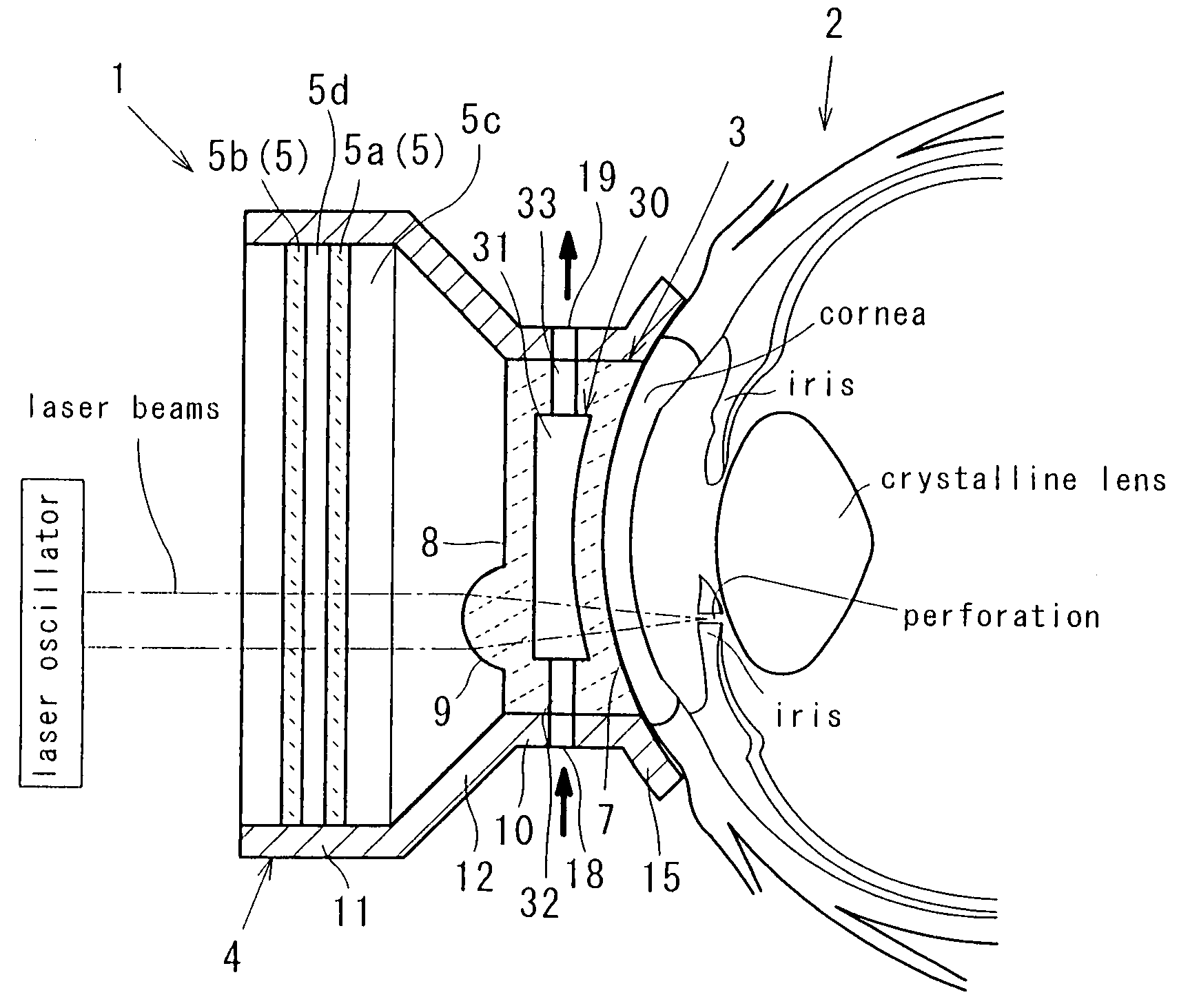
[0067]Referring to FIG. 1, described is an ophthalmic laser treatment device 1 according to a first embodiment of the invention. FIG. 1 shows a schematic view of the ophthalmic laser treatment device 1 which is placed in contact with an eyeball 2. In FIG. 1, an up-to-down line from top to bottom accords to a gravitational direction, and the left side of the drawing is where a laser oscillator is located. The right side of the drawing is where the eyeball resides, an upper side is a parietal side and the lower side is a maxillary side.

[0068]The ophthalmic laser treatment device 1 introduces laser beams from the laser oscillator to the eyeball 2 of a subject patient, and having a lens 3 which collects the laser beams and brings the laser beams into focus on the eyeball 2. In ophthalmic laser treatment device 1, a lens holder 4 is provided to structurally support the lens 3. A transparent partition wall 5 is provided to form a hermetic space...

modification form

of the First Embodiment of the Invention

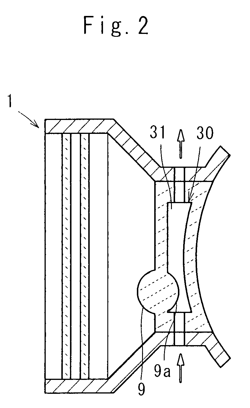
[0086]In the modification form of the first embodiment of the invention as shown in FIG. 2, a lower side of the convex portion 9 of the lens 3 has a convex surface 9a projected into the hollow chamber 31 to form a convexo-convex lens. Instead of the columnar hollow chamber 31, an annular hollow chamber may be provided as shown in FIG. 3. Instead of hollowing out the inner portion of the lens 3 upon forming the hollow chamber 31, two dish-shaped transparent members may be joined in a face-to-face fashion to define the hollow chamber 31 inside the joined dish-like members.

[0087]It is to be noted that the fluid is permeable to the laser beams in the first embodiment of the invention, however, the fluid may be impermeable to the laser beams when the inner passage 30 is provided out of a permeative path of the laser beams.

second embodiment

of the Invention

Structure of Second Embodiment

[0088]FIG. 4 shows a second embodiment of the invention which mainly describes the structure other than the first embodiment of the invention. The contact condition between the eyeball 2 and the lens 3 in the second embodiment of the invention, is substantially identical to the contact condition in the first embodiment of the invention.

[0089]In the second embodiment of the invention, an outer side passage 40 is provided to flow the fluid along an outer circumference of the lens 3.

[0090]Along an entire length of the outer circumference of the lens 3, a circumferential groove 41 is provided. By liquid-tightly covering the circumferential groove 41 by the inner surface of the holder cylinder 10, the outer side passage 40 is defined at the outer circumference of the lens 3. The holder cylinder 10 provides the inlet hole 18 and the outlet hole 19. The inlet hole 18 permits the entrance of the fluid, and the outlet hole 19 permits the exhaust ...


PUM


Abstract

A light-permeable member (lens 3) is provided to lead laser beams to an eyeball (2), and a spacer member (refrigerator forming portion 14) is provided to maintain a predetermined space (refrigerator chamber 13) between the light-permeable member (lens 3) and the eyeball (2). The eyeball (2) is cooled by introducing a fluid into the space (refrigerator chamber 13) so as to cool the eyeball (2) while applying the laser beams to the eyeball (2). The laser beams of higher intensity is applied with an occurrence of keratoedema reduced, while at the same time, preventing the complication which otherwise would be caused due to the heat generation of the eyeball (2).

Description

FIELD OF THE INVENTION[0001]The invention relates to a device used for an ophthalmic laser treatment by making use of laser beams, and especially concerns to an ophthalmic laser treatment device used for an laser iridoctomy.BACKGROUND OF THE INVENTION[0002]Upon performing a trans-corneal laser treatment in an ophthalmology, an cornea-contact type ocular lens has been used, so that laser beams released from a laser oscillator can reach inside the eyeball via the ocular lens and cornea in order to draw a therapeutical effect.[0003]The laser treatment ocular lens is represented by an iridoctomy ocular lens as disclosed by Japanese Laid-open Patent Application No. 63-29639. The ocular lens is such that a laser-incident side lens and a laser-radiant side lens (eyeball-contact side lens) are accommodated into a lens holder, and prevent the outside light from entering inside the eyeball. When the laser is applied to the ocular lens with the lens placed on the eyeball, the lens enables an o...

Claims


Application Information

Patent Timeline
Patent Type & Authority Applications(United States)
IPC IPC(8): A61B18/20
CPCA61B2018/00023A61F9/008A61F2009/00891A61F2009/00876A61F9/009
Inventor KATAOKA, TAKUYA
Owner KATAOKA TAKUYA
Learn More