
engine cooling structure

A technology of cooling structure and engine, applied in the direction of engine cooling, engine components, machine/engine, etc., can solve the problems of no disclosure of the radiator hose installation structure and difficult transmission of vibration in the intake passage.

Active Publication Date: 2022-01-11
TOYOTA JIDOSHA KK
View PDF11 Cites 0 Cited by
  • Summary
  • Abstract
  • Description
  • Claims
  • Application Information

AI Technical Summary

Problems solved by technology

According to the technique described above, the vibration from the vehicle or the engine is hardly transmitted to the intake passage
However, Patent Document 1 only refers to the installation structure of the intake passage, and Patent Document 1 does not disclose anything about the installation structure of the radiator hose.
[0011] In other words, conventionally, there is no technology that can prevent the failure of the connecting pipe caused by the vibration of the engine when fixing the connecting pipe provided on the radiator hose to the engine.

Method used


Image

  • engine cooling structure
  • engine cooling structure
  • engine cooling structure

Examples


Embodiment Construction

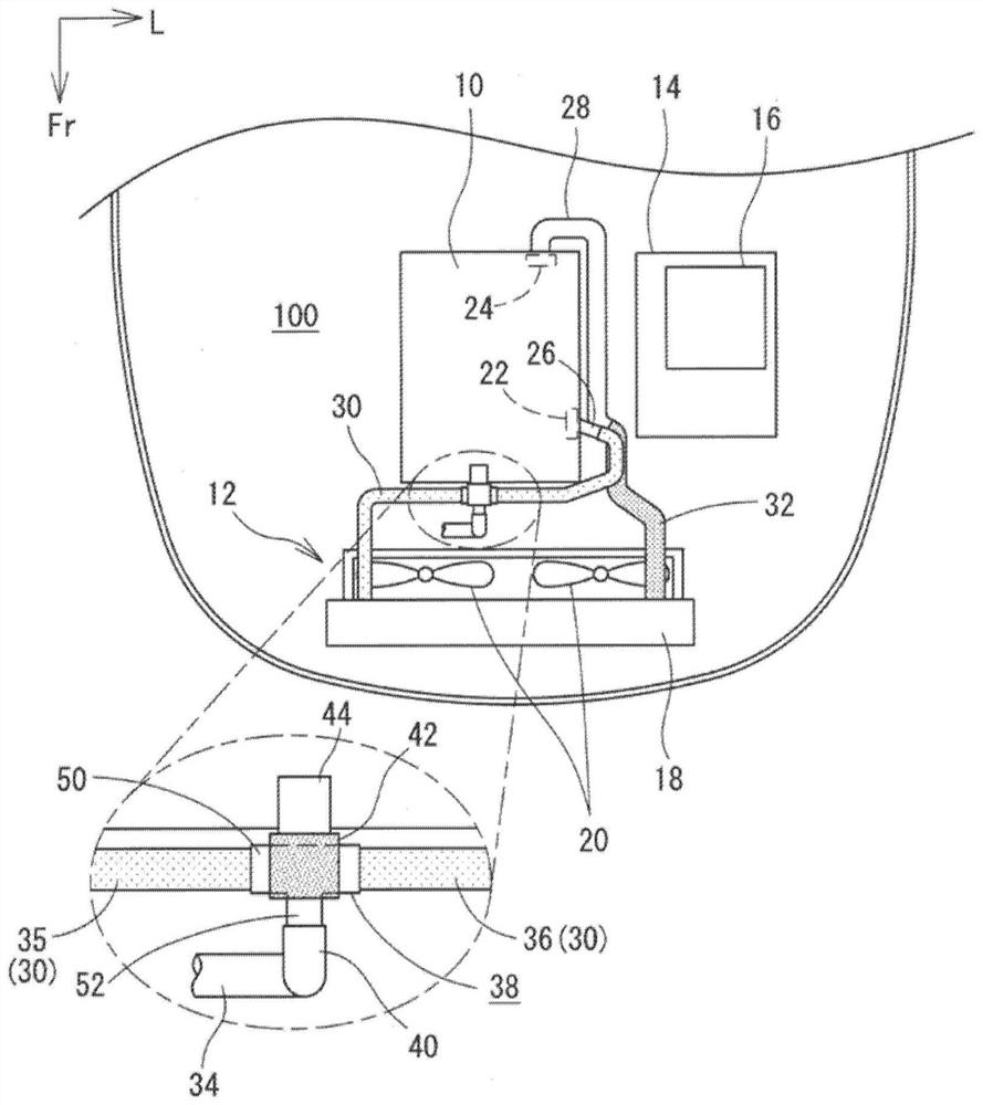
[0034] Hereinafter, the cooling structure of the engine 10 will be described with reference to the drawings. figure 1 It is a schematic plan view of the front part of a vehicle. It should be noted that, in figure 1 In the drawing, the outlet pipe 28 is shown thicker than the inlet pipe 26 in order to easily distinguish the inlet pipe 26 and the outlet pipe 28 , but actually the two pipes 26 and 28 have the same diameter. Likewise, the outlet hose 32 is shown thicker than the inlet hose 30, but in reality both hoses 30, 32 are of the same diameter. Moreover, in figure 1 , figure 2 In , light ink is applied to the inlet hose 30 and thick ink is applied to the outlet hose 32 .

[0035] This vehicle is a hybrid vehicle having an engine 10 and an electric motor as power sources for driving the vehicle. However, the technology disclosed in this specification is not limited to a hybrid vehicle, and may be applied to a vehicle having only engine 10 as a power source.

[0036] S...


PUM


Abstract

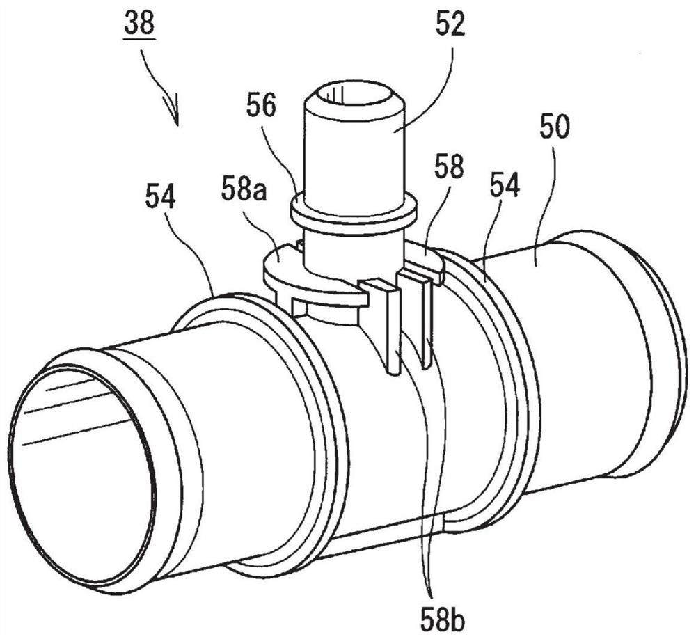
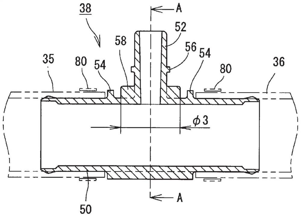
The invention provides a cooling structure of an engine. The cooling structure of the engine (10) that cools the engine (10) with the coolant supplied from the radiator (12) and cools the coolant discharged from the engine (10) with the radiator (12) includes: A pipe (30), one end connected to the engine (10) and the other end connected to the radiator (12), has more than two hose components (35, 36) and connects the two or more hose components (35, 36) a connected connecting pipe (38); and a clamping member (42) having a pipe-side connecting portion connected to the connecting pipe (38) and an engine-side connecting portion directly or indirectly connected to the engine (10) part, the clamp (42) has a function as a transmission suppressing part that suppresses the transmission of vibration from the engine side connection part to the connection pipe (38) between the clamp (42) and the connection pipe (38). gap.

Description

technical field [0001] This specification discloses an engine cooling structure that cools an engine with coolant supplied from a radiator and cools coolant discharged from the engine through the radiator. Background technique [0002] An engine cooling structure in which an engine is cooled by a coolant supplied from a radiator and a coolant discharged from the engine is cooled by a radiator is widely known. In the above cooling structure, a radiator hose through which the coolant flows is provided between the radiator and the engine. [0003] The aforementioned radiator hose is longer than the distance between the radiator and the engine. Therefore, in the middle part of the radiator hose away from the fixed end connected to the engine or the radiator, the radiator hose moves and tends to vibrate greatly. When the radiator hose vibrates greatly in the middle part, it interferes with other components, and other components and / or the radiator hose may deteriorate or be dam...

Claims


Application Information

Patent Timeline
Patent Type & Authority Patents(China)
IPC IPC(8): F01P11/04F16L3/10
CPCF01P11/04F16L3/1075F01P3/12F01P7/14F01P2003/001
Inventor 小林翼岩濑友志奥野博之友广匡
Owner TOYOTA JIDOSHA KK
Learn More