Coupling structure for optical fibres and process for making it
a technology of optical fibres and coupling structures, applied in the field of coupling structures for optical fibres and process for making them, can solve the problem that the end surface of optical fibres cannot be brought sufficiently close to the optical device to make a low-loss optical connection, and achieve the effect of limiting diffusion or diffraction, and optimising coupling efficiency
- Summary
- Abstract
- Description
- Claims
- Application Information
AI Technical Summary
Benefits of technology
Problems solved by technology
Method used
Image
Examples
first embodiment
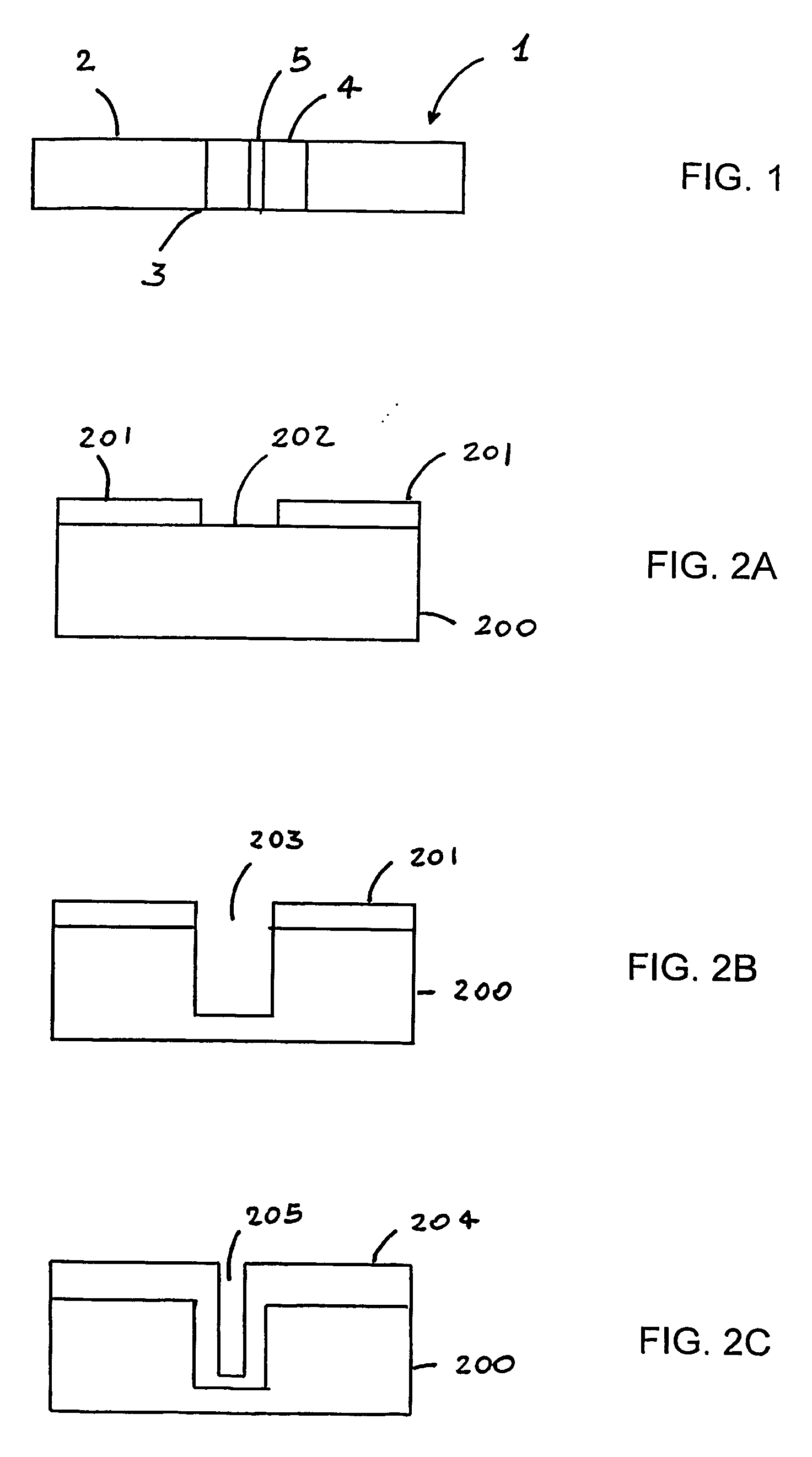
[0058]FIG. 1 illustrates a first preferred embodiment of the coupling structure for coupling an optical fibre to an optical device according to the present invention. Coupling structure, the guidance element 1, comprises a monocrystalline silicon (c-Si) substrate 2 having formed therein a SiO2-based optical through-via 3, or guidance channel, which includes a channel cladding 4 and a channel core 5. In the preferred embodiment, the channel core 5 is substantially made of SiO2 having a refractive index larger than the refractive index of the SiO2 which substantially forms the channel cladding 4. Preferably, the difference in refractive index between the core and the dad channels is of 0.5-0.8%. As it will become clear from the following description, the optical fibre will be coupled to the guidance channel of the guidance element 1 so that the core of the fibre will substantially correspond to the channel core of the guidance channel. Light transmitted from or to the optical fibre wi...
second embodiment
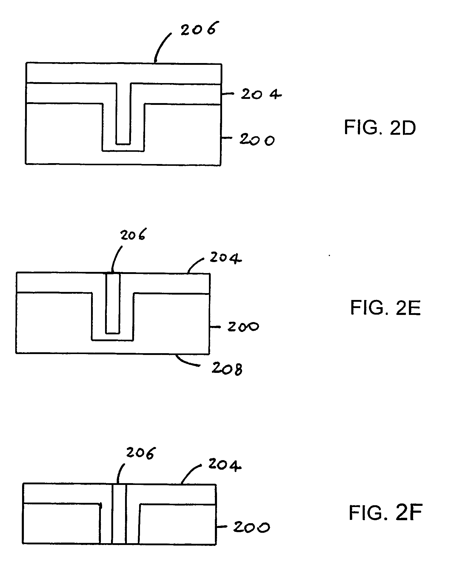
[0062]According to a second embodiment of the present invention, the coupling structure comprises a graded-index guidance channel. FIGS. 3A-3H illustrate the process steps that can be used to obtain the coupling structure with a graded-index channel shown in FIG. 3H. An opening 302 is defined in a silicon oxide mask 301 on a silicon substrate 300 (FIG. 3A). The silicon substrate is for example a 6″ c-Si 675 μm-thick wafer. Preferably, opening 302 is circular and has a diameter about twice the diameter of the desired channel core of the coupling structure. For example, in order to obtain a 9-μm channel core diameter, opening 302 is chosen to be about 18 μm. A deep trench 303 is formed in the silicon substrate 300 through opening 302 by etching, preferably by dry etching (FIG. 3B). Preferably, trench 303 has “sloped” sidewalls. For example, deep reactive ion etching (RIE) is carried out at a temperature of 20° C. for 1 h to form a 200 μm deep trench having a wall taper angle α of 87-8...
third embodiment
[0065]According to a third embodiment of the present invention, the coupling structure comprises a coaxial guidance channel. A silicon oxide layer is grown on a c-Si substrate 400. The silicon oxide 401 is patterned by means of a lithographic mask so as to expose the areas where the trenches are to be formed (FIG. 4A). A non-exposed annular surface 402 is interposed between a first circular opening 411 and an external annular opening 412. The exposed areas are then etched, e.g., by dry etching, to form deep trenches 403 and 404 (FIG. 4B). In a preferred embodiment, trench 404 has a diameter of about 18 μm and external annular trench 403 has a width of about 15 μm. The annular region underneath the non-etched annular surface 402 is preferably 7 μm wide. The oxide 401 is then removed. In a subsequent step, a relatively thick SiO2 layer 405 of refractive index n1 is thermally grown on the substrate surface and within the trenches so as to fully oxidise the annular wall corresponding to...
PUM
 Abstract
Description
Claims
Application Information
 - R&D
- Intellectual Property
- Life Sciences
- Materials
- Tech Scout
- Unparalleled Data Quality
- Higher Quality Content
- 60% Fewer Hallucinations
Browse by: Latest US Patents, China's latest patents, Technical Efficacy Thesaurus, Application Domain, Technology Topic, Popular Technical Reports.
© 2025 PatSnap. All rights reserved.Legal|Privacy policy|Modern Slavery Act Transparency Statement|Sitemap|About US| Contact US: help@patsnap.com


