Offset compensator and optical disc drive using the same

a compensator and optical disc technology, applied in the field of read signal processing system for optical disc drive, can solve the problems of adversely affecting the decoding in some cases, the performance of pll and viterbi decoders is deteriorated, and the conventional dfb slicer cannot correctly determine the shortest mark and space in a read signal, etc., to achieve sufficient reproduction performance, reduce inter-layer interference of dual-layer disc, and reduce signal noise

Inactive Publication Date: 2009-05-28
HITACHI CONSUMER ELECTRONICS CORP +1
View PDF12 Cites 5 Cited by
  • Summary
  • Abstract
  • Description
  • Claims
  • Application Information

AI Technical Summary

Benefits of technology

[0031]A preferred aspect includes a means for limiting the absolute value of an offset signal inputted to the integrator and a means for limiting the absolute value of an offset compensation signal. It is also effective to provide a means for removing a pseudo-edge from a phase comparison and offset detection using a differential signal of the read signal. Further, it is also effective to provide a means for reducing noise of a signal inputted to a phase detector or a means for observing the locked state of a PLL and controlling the operation of the JFB offset compensator according to the state thereof.
[0032]The present invention guarantees a sufficient reproduction performance even in the case where the linear recording density is high, the resolution of the shortest mark and space is zero, and the read signal has an asymmetry. Also, the local offset variation such as the inter-layer interference of a dual-layered disc is reduced.

Problems solved by technology

In the case where the linear recording density is high and the resolution of the shortest mark and space is zero, a conventional DFB slicer cannot correctly determine the shortest mark and space in a read signal.
Particularly, in the case where a read signal has an asymmetry, the DFB slicer may return a significantly erroneous result, thereby adversely affecting the decoding in some cases.
As described above, when the DC component is superimposed on the read signal, the performances of a PLL and a Viterbi decoder are deteriorated.
Consequently, the DFB slicer cannot cope with the DC component variation due to the inter-layer interference or the like.
Thus, it is difficult to compensate for the DC component variation with this system alone.
In the case where the amplitude of the superimposed DC component is extremely large, there is a problem that the two points sandwiching the zero level depart from the position of the real edge whereby a wrong result is obtained.
Thus, an adaptive Viterbi decoder is also not suitable for coping with the local DC component variation such as the inter-layer interference.

Method used


Image

  • Offset compensator and optical disc drive using the same
  • Offset compensator and optical disc drive using the same
  • Offset compensator and optical disc drive using the same

Examples


Embodiment Construction

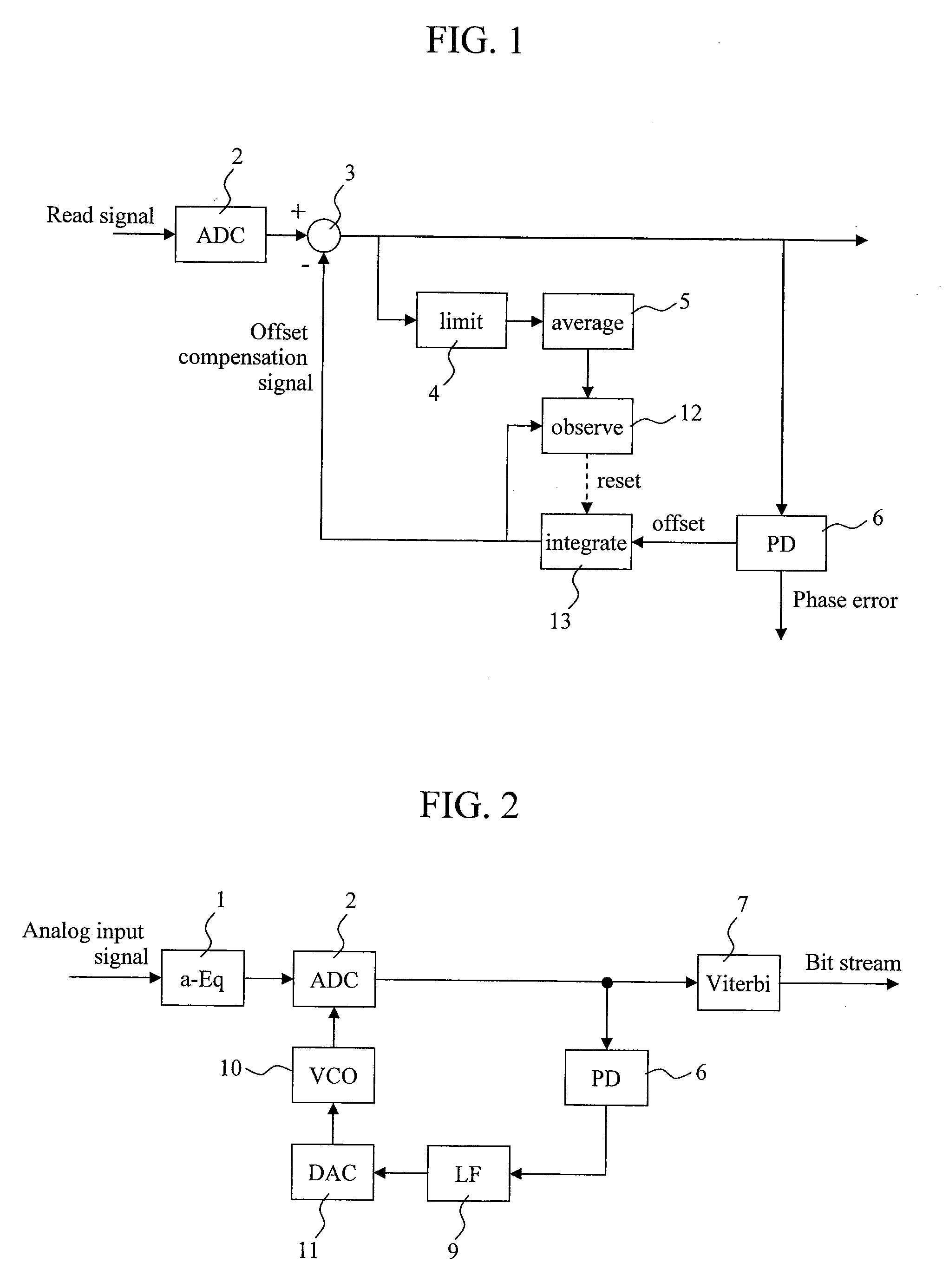
[0054]FIG. 1 shows one example of an offset compensator according to the present invention. FIG. 1 depicts only portions necessary for carrying out the present invention, and other read signal processing systems are omitted for simplification.

[0055]In the present invention, a system for removing an offset component from a read signal is based on a JFB offset compensator. Specifically, an analog read signal is converted to a digitized read signal by an AD converter 2, then added to an offset compensation signal in a subtractor 3, and inputted to a phase detector 6. The phase detector 6 outputs a phase error and simultaneously outputs an offset component of each edge as described in the Description of the Related Art. The offset component is smoothed by an integrator 13, whereby the smoothed result becomes the offset compensation signal. So far, it is the same as the conventional JFB offset compensator.

[0056]A feature of the present invention is that a means for preventing a pseudo-lo...


PUM

PropertyMeasurementUnit
lengthaaaaaaaaaa
timeaaaaaaaaaa
linear recording densityaaaaaaaaaa

Abstract

The generation of a pseudo-lock is prevented in a JFB offset compensator whose use has been conventionally limited due to a tendency to generate the pseudo-lock, and performance degradation of a PLL and a Viterbi decoder is suppressed. A means for monitoring an offset of a read signal is provided independently from the JFB offset compensator. With this configuration, the generation or a possibility of the generation of the pseudo-lock can be detected to reset an integrator. In order to reduce the influence of a large sporadic offset triggering the pseudo-lock, there may also be provided a limitter for limiting the absolute value of an offset signal inputted to the integrator or a limitter for limiting the absolute value of an offset compensation signal.

Description

CLAIM OF PRIORITY[0001]The present application claims priority from Japanese patent application JP 2007-296768 filed on Nov. 15, 2007, the content of which is hereby incorporated by reference into this application.BACKGROUND OF THE INVENTION[0002]1. Field of the Invention[0003]The present invention relates to a read signal processing system for an optical disc drive.[0004]2. Description of the Related Art[0005]The application range of the present invention is not limited to Blu-ray Discs (hereinafter referred to as “BDs”), but the description below is based on a BD and terms are basically those used for BDs.[0006]As of 2007, a BD is a commercially available optical disc with the largest capacity among those in practical use. The surface recording capacity of an optical disc is primarily limited by the size of an optical spot on a recording layer used for recording and reproduction. The size of the optical spot is mainly determined by the wavelength of light and the numerical apertur...

Claims


Application Information

Patent Timeline
Patent Type & Authority Applications(United States)
IPC IPC(8): G11B7/0045G11B27/36
CPCG11B7/005G11B20/10009G11B20/10037G11B2020/1457G11B20/10425G11B20/1403G11B2007/0013G11B20/10203
Inventor KIKUGAWA, ATSUSHI
Owner HITACHI CONSUMER ELECTRONICS CORP
Why Eureka
Try Eureka