Drive mechanism and optical head
a drive mechanism and optical head technology, applied in the direction of instruments, manufacturing tools, gearing, etc., can solve the problems of contributing to the downsizing of the overall drive mechanism, and achieve the effect of good stability and reducing unnecessary vibrations
- Summary
- Abstract
- Description
- Claims
- Application Information
AI Technical Summary
Benefits of technology
Problems solved by technology
Method used
Image

Examples
embodiment 1
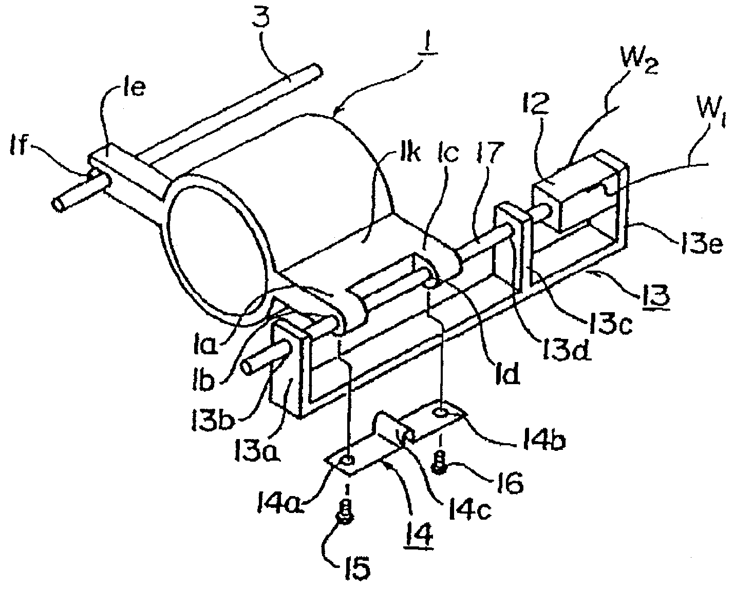
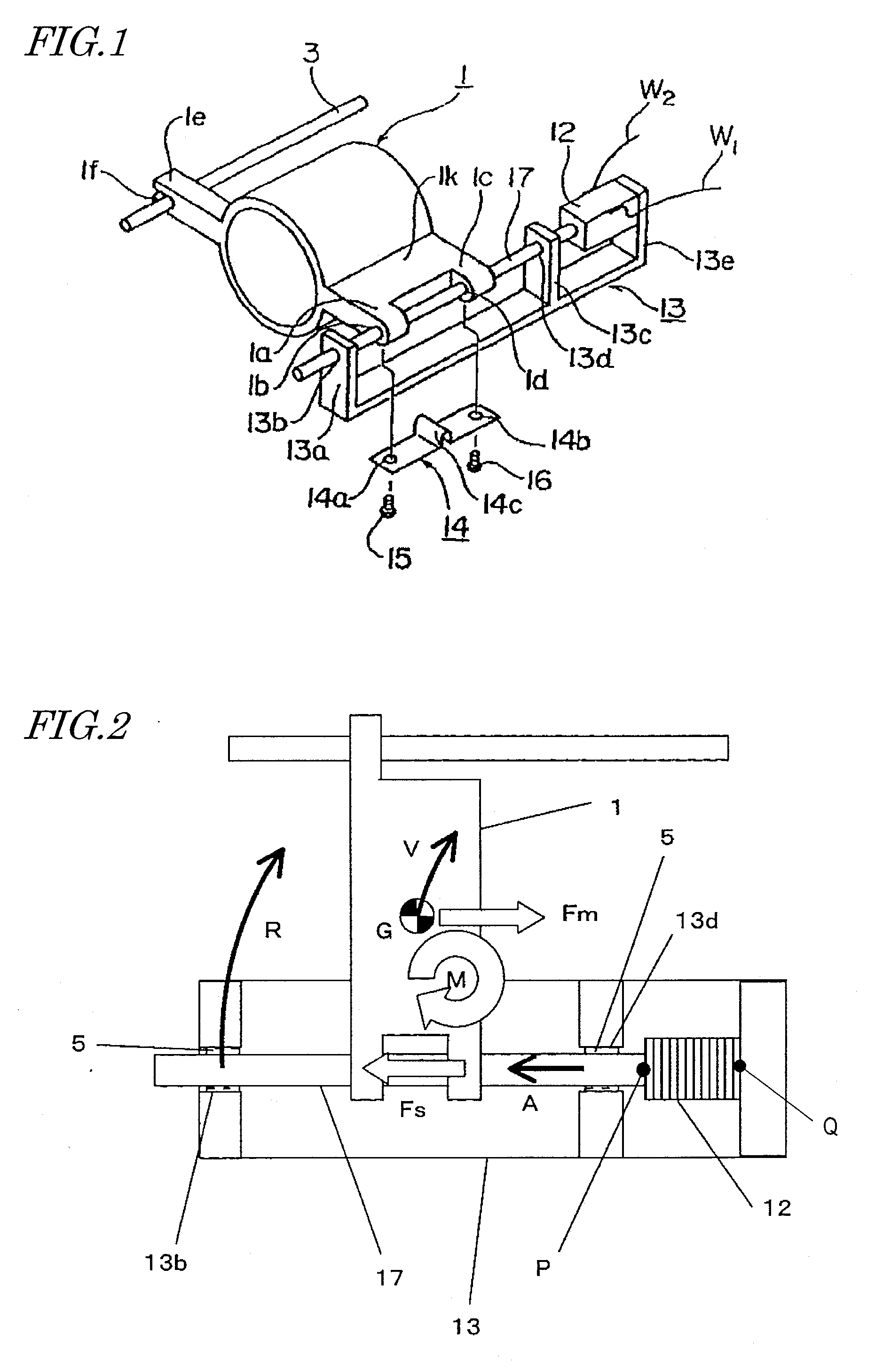
[0068]FIG. 1 is a perspective view illustrating a first preferred embodiment of a drive mechanism according to the present invention. The Drive Mechanism of this Preferred embodiment includes a mover 1, a drive body 17, a drive element 12, and a base member 13.
[0069]The drive mechanism of this preferred embodiment is provided for an optical head in order to drive an optical element such as a lens, which is arranged along an optical path in an optical system, and to adjust its position. For that purpose, the mover 1 has a built-in optical element (not shown).
[0070]The drive body 17 defines a longitudinal direction and preferably has a shaft shape. As viewed on a plane that is perpendicular to the longitudinal direction, the drive body 17 may have a circular or polygonal cross section. In this preferred embodiment, the drive body 17 has a circular cross section.
[0071]The mover 1 includes a supporting plate portion 1k and an arm 1e, which both protrude horizontally and extend in mutual...
embodiment 2
[0096]FIG. 6 illustrates a second preferred embodiment of the drive mechanism. This second preferred embodiment is different from the first preferred embodiment described above in that the hole 13d of the bearing portion closer to the drive element 12 is not filled with the viscoelastic body 5.
[0097]As already described for the first preferred embodiment, the drive body 17 is displaced more greatly, and the vibrations of the drive body 17 perpendicular to the longitudinal direction thereof can be damped more effectively, at the bearing portion 13b. That is why this second preferred embodiment is effectively applicable to a situation where the amount of the viscoelastic body 5 to be injected should be limited due to cost, assembling or any other consideration. This preferred embodiment would achieve the same effects as those of the first preferred embodiment described above.
[0098]Comparing the displacements inside the holes 13b and 13d of the bearing portions to each other, the displ...
embodiment 3
[0099]FIGS. 7A and 7B illustrate the principal portion of a third preferred embodiment of the drive mechanism.
[0100]This preferred embodiment is different from the first preferred embodiment in the structure of the bearing portion 13a of the base member 13. More specifically, the bearing portion 13a has a hole 23b, to which the drive body 17 is inserted, and a chamfered portion 6 at the opening of the hole 23b.
[0101]As in the first preferred embodiment described above, the hole 23b is defined by a cylindrical inner face (corresponding to the first surface). This inner face defines a circle, of which the diameter is slightly greater than that of the circular cross section of the drive body 17. The inner face is located with a predetermined very small gap left with respect to the side surface of the drive body 17. The chamfered portion 6 is defined by a tapered inner face (corresponding to the second surface) and the gap between the chamfered portion 6 and the side surface of the dri...
PUM
 Abstract
Description
Claims
Application Information
 - Generate Ideas
- Intellectual Property
- Life Sciences
- Materials
- Tech Scout
- Unparalleled Data Quality
- Higher Quality Content
- 60% Fewer Hallucinations
Browse by: Latest US Patents, China's latest patents, Technical Efficacy Thesaurus, Application Domain, Technology Topic, Popular Technical Reports.
© 2025 PatSnap. All rights reserved.Legal|Privacy policy|Modern Slavery Act Transparency Statement|Sitemap|About US| Contact US: help@patsnap.com