
NOx CONTROL SYSTEMS AND METHODS FOR CONTROLLING NOx EMISSIONS

a control system and nox technology, applied in the direction of exhaust treatment electric control, machines/engines, lighting and heating apparatus, etc., can solve the problems of reducing the effect of nox emissions

Inactive Publication Date: 2009-05-28
MICHIGAN TECHNOLOGICAL UNIVERSITY
View PDF12 Cites 34 Cited by
  • Summary
  • Abstract
  • Description
  • Claims
  • Application Information

AI Technical Summary

Benefits of technology

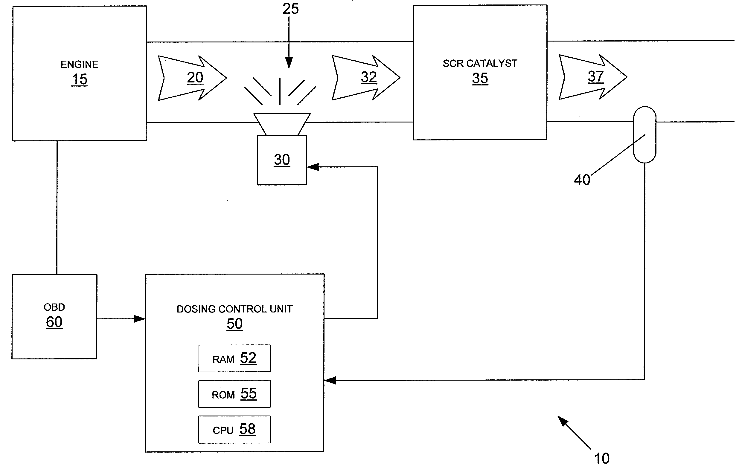
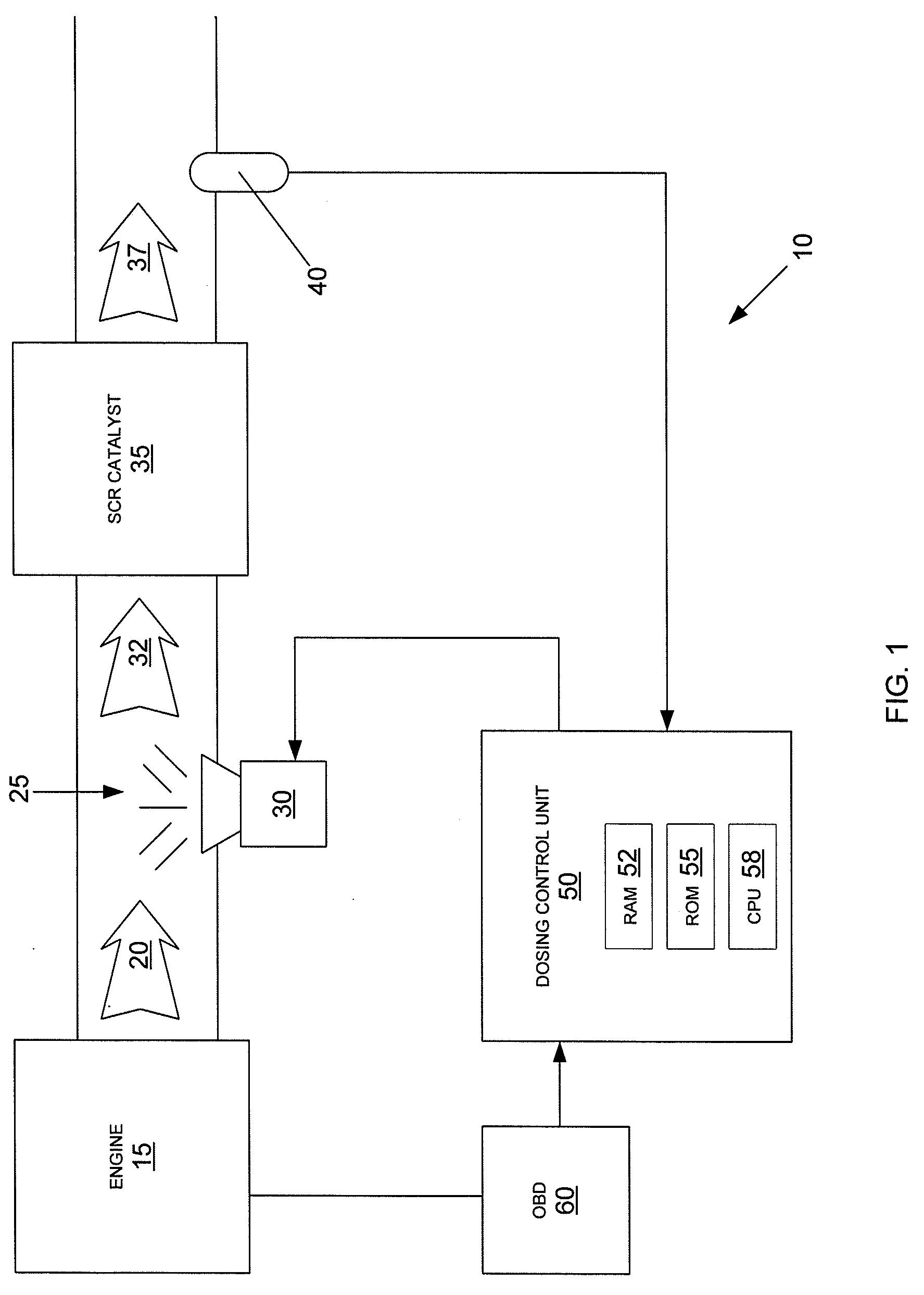
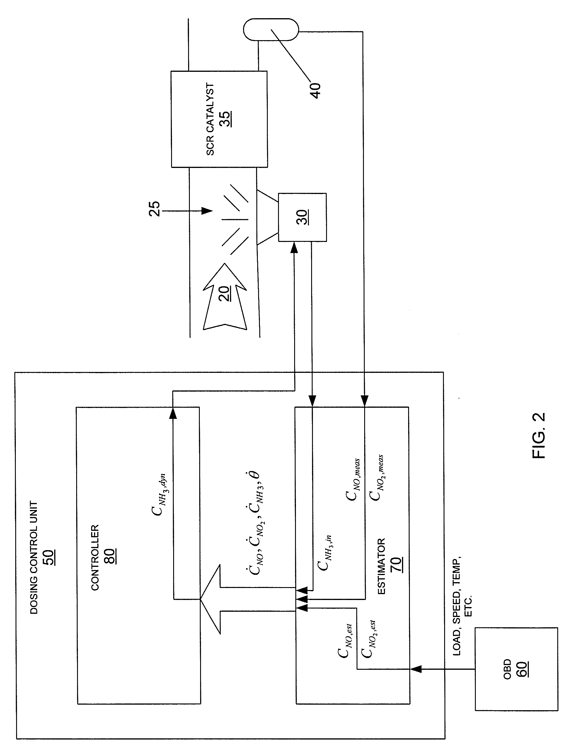
[0007]In one embodiment, the invention comprises an exhaust aftertreatment control system for exhaust gases. The exhaust aftertreatment control system comprises a selective catalytic reduction (SCR) catalyst in fluid communication with an exhaust stream from an engine, a urea solution injector, upstream of the SCR catalyst, in fluid communication with the exhaust stream, a gas sensor, downstream of the SCR catalyst, in fluid communication with the exhaust stream, a diagnostic unit, operatively connected to the engine, and a dosing control unit, operatively connected to the gas sensor, the urea solution injector, and the diagnostic unit. The dosing control unit receives a signal indicative of NO, NO2 or NH3 concentrations from the gas sensor, receives a signal indicative of engine parameters from the diagnostic unit, converts the engine parameters to NO and NO2 concentrations, estimates NO and NO2 concentrations downstream from the SCR catalyst, estimates the fractional surface coverage of NH3 in the SCR catalyst, calculates a quantity of urea solution needed to minimize NOx emissions, and signals the urea solution injector to inject the quantity of the urea solution into the exhaust stream.

Problems solved by technology

Nitrogen oxides are key ingredients in the formation of photochemical smog, which damages respiratory functions and limits visibility.
Additionally, nitrogen oxides form nitric acid when they react with moisture in the atmosphere, thus forming acid rain.
Additionally, NO2-producing processes present a greater health risk than NO-producing processes, as is reported in the literature.

Method used


Image

  • NOx CONTROL SYSTEMS AND METHODS FOR CONTROLLING NOx EMISSIONS
  • NOx CONTROL SYSTEMS AND METHODS FOR CONTROLLING NOx EMISSIONS
  • NOx CONTROL SYSTEMS AND METHODS FOR CONTROLLING NOx EMISSIONS

Examples


example 1

Verification of Four-State Model

[0063]FIG. 5 depicts an experimental setup in accordance with the invention. A Navistar I6 7.6 L diesel engine 210 was connected to a diesel oxidation catalyst 230 and a catalyzed particulate filter 240, and then outfitted with urea injector 30 and a first SCR catalyst 35 and a second SCR catalyst 38. [Generally an exhaust aftertreatment system would have only one SCR catalyst, as is depicted in FIG. 1.] The exhaust concentrations of NO and NO2 were measured before first SCR catalyst 35 with a first emission test bench 250 and after second SCR catalyst 38 with a second emission test bench 255. The NH3 concentrations were measured before first SCR catalyst 35 with a first Fourier Transform Infrared Spectrometer (FTIR) 260 and after second SCR catalyst 38 with a second Fourier Transform Infrared Spectrometer (FTIR) 265.

[0064]Engine 210 was run at a variety of speed and load conditions as shown in FIG. 6, resulting in a variety of engine temperatures and...

example 2

Controlling NOx Emissions From Industrial Burner

[0068]FIG. 10 is a block diagram of a prophetic embodiment of an exhaust aftertreatment system 310 employing a NOx sensor according to the principles of the invention. The exhaust aftertreatment system 310 will include a urea injector 30, a selective catalytic reduction (SCR) catalyst 35, a NOx sensor 40, and a dosing control unit 50. An oil-fueled industrial burner 315 (used to power a 66 MW steam generator) will produce an exhaust stream 20 containing nitrogen oxides, including NO and NO2. Exhaust stream 20 will move through aftertreatment system 310, exhaust stream 20 will be mixed with an atomized urea solution 25 from urea injector 30 to create urea-enriched exhaust 32. Urea-enriched exhaust 32 will then enter SCR catalyst 35. SCR catalyst 35 will contain metal zeolites arranged in a honeycomb such that the passing exhaust gasses will interact with a multitude of catalytic sites. As urea-enriched exhaust 32 is swept into SCR catal...


PUM


Abstract

An exhaust aftertreatment system comprising a selective reduction catalyst, a NOx sensor or an NH3 sensor, a urea injector, and a dosing control unit, wherein the dosing control unit calculates the rate of urea injection by estimating the concentrations of NO and NO2 in the exhaust downstream of the SCR catalyst.

Description

CROSS-REFERENCE TO RELATED APPLICATIONS[0001]This application claims priority to U.S. Provisional Patent Applications Ser. Nos. 60 / 990,211, filed Nov. 26, 2007, and 61 / 052,759, filed May 13, 2008, both of which are incorporated herein by reference in their entirety.FIELD OF INVENTION[0002]The present invention relates to methods for reducing nitrogen oxide emissions from combustion processes. In particular, the invention relates to the use of catalysts in combination with an ammonia-precursor injector to reduce nitrogen oxide emissions from engines, such as those used by diesel-powered vehicles, equipment, and generators.BACKGROUND[0003]Nitrogen oxides (NOx) are a well-known class of atmospheric pollutants that pose risks to human health, agriculture, and property. Nitrogen oxides are key ingredients in the formation of photochemical smog, which damages respiratory functions and limits visibility. Additionally, nitrogen oxides form nitric acid when they react with moisture in the at...

Claims


Application Information

Patent Timeline
Patent Type & Authority Applications(United States)
IPC IPC(8): F01N9/00
CPCF01N3/035F01N13/0093F01N3/208F01N2560/021F01N2560/026F01N2610/02F01N2610/146F01N2900/08F01N2900/14F01N2900/1402F01N2900/1622F23J15/003F23J15/02F23J2219/10Y02T10/24F01N13/009F01N3/106Y02T10/12
Inventor DEVARAKONDA, MARUTHIPARKER, GORDONJOHNSON, JOHN
Owner MICHIGAN TECHNOLOGICAL UNIVERSITY
Learn More