Log building

Active Publication Date: 2009-05-28
WRIGHTMAN ROBERT A
View PDF37 Cites 32 Cited by
  • Summary
  • Abstract
  • Description
  • Claims
  • Application Information

AI Technical Summary

Benefits of technology

[0012]According to the present invention, there is provided a log wall having a plurality of logs stacked one above another, a tie bolt extending through said logs between a pair of fastenings, a spring acting between one of said fastenings

Problems solved by technology

Practically, however, this rarely occurs and there is a difference in the shrinkage rate between logs and even within a particular log in a wall.
The sealing material between the logs accommodates variations in the shrinkage but if the shrinkage is too great, a gap may occur between the logs.
This arrangement provides initial compression and settling of the logs but does not accommodate the shrinkage that occurs as the logs dry.
Whilst this arrangement provides a continuing tension in the rod, it does not inhibit relative movement between the logs due to forces sufficient to overcome the spring.
Such forces are significant and the downward force provided by the spring is insufficient to resist these forces.
Accordingly, the provision of a simple spring does not maintain the integrity of the wall in typical situations.
In theory, this arrangement would inhibit separation of the logs but in practice, there is no continuing control over the relative movement between the logs.
Moreover, progressive cupping of the logs due to the inherent stresses will not be controlled, allowing the gaps between the logs to open up along the length of the log.

Method used


Image

  • Log building
  • Log building
  • Log building

Examples


Embodiment Construction

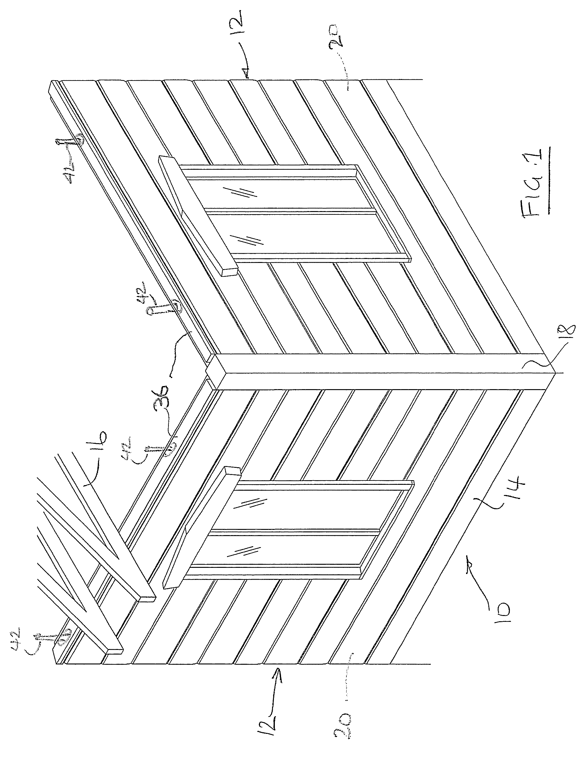
[0022]Referring therefore to FIG. 1, a log building generally indicated at 10 includes log walls 12 supported on a foundation 14 and carrying a roof structure 16. The walls 12 intersect at corners 18 and are interconnected either by overlapping joints or by the provision of a post and a butt joint. The various ways in which the corners 18 may be formed is well known in the log building art and need not be described in further detail. A particular beneficial form of corner structure is shown in US Patent Application filed Aug. 28, 2007 titled “Log Wall Connector System”, the contents of which are incorporated herein by reference. It will also be appreciated that whereas external walls are shown in FIG. 1, the preferred embodiment may also be used on internal walls.

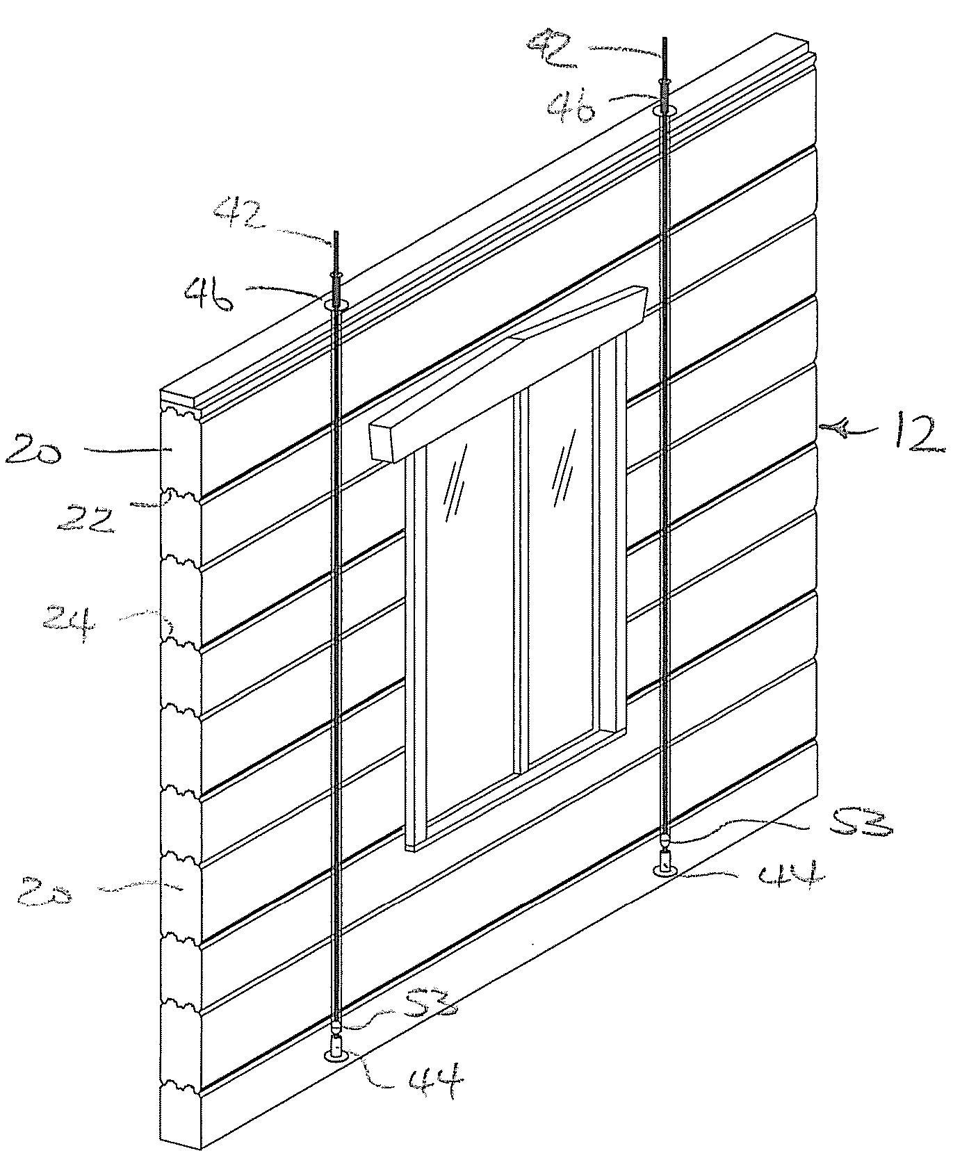
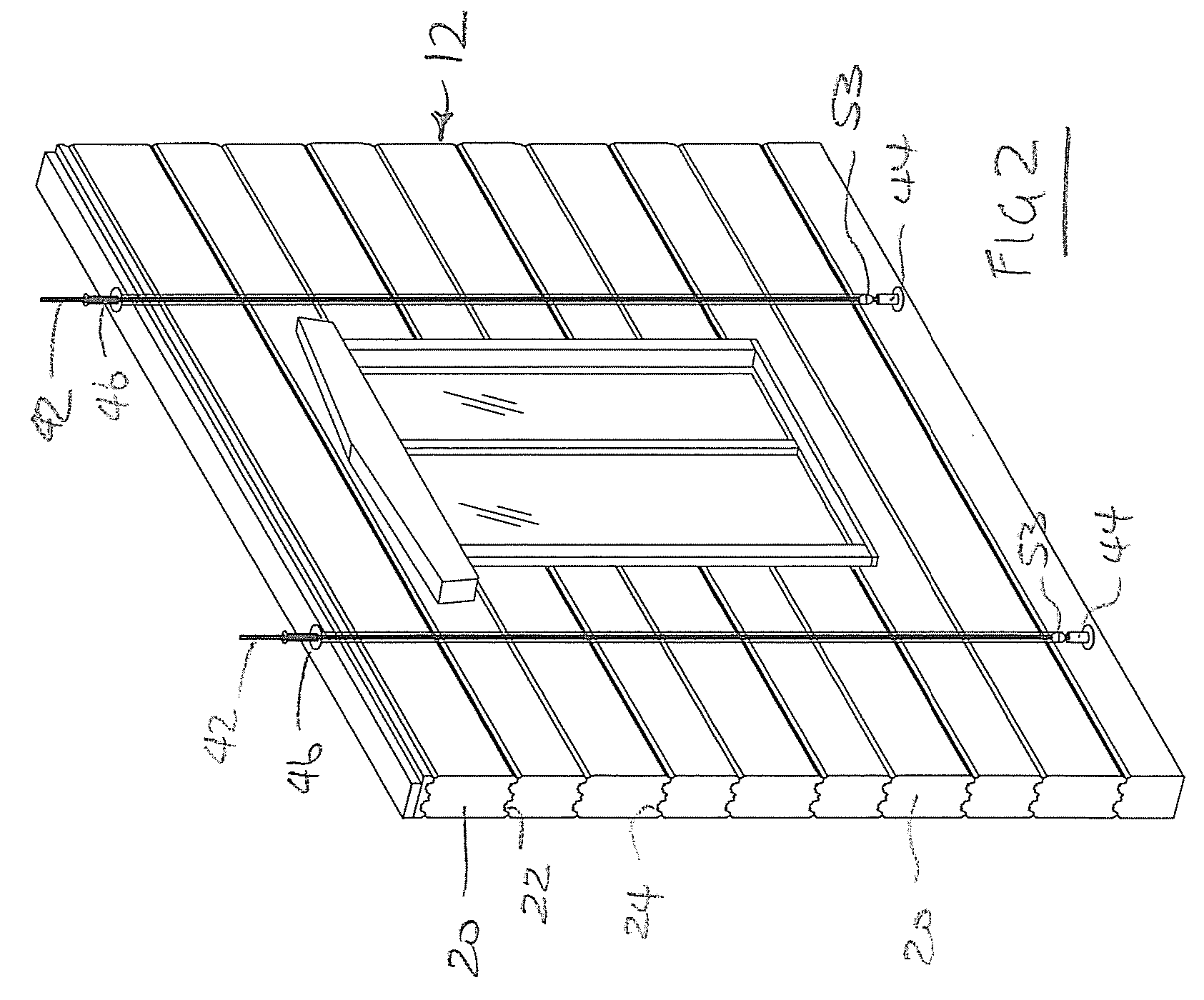
[0023]Referring to FIG. 2, each of the log walls 12 is formed from logs 20 having abutting upper and lower faces 22, 24 respectively. As shown in FIG. 3, the upper and lower faces 22, 24 are formed with inter-engaging tongu...


PUM


Abstract

A tie bolt assembly for a log building has a coil spring that applies a continuous compressive load to force the logs together. Subsequent expansion or separation of the logs is prevented by a ratchet mechanism acting between the tie bolt and log.

Description

CROSS REFERENCE TO RELATED APPLICATION[0001]This application claims priority from U.S. Provisional Application No. 60 / 972,055 filed on Sep. 13, 2007 all of which are hereby incorporated by reference.FIELD OF THE INVENTION[0002]The present invention relates to log buildings.DESCRIPTION OF THE PRIOR ART[0003]It is well known to construct a building using horizontal logs as wall members. The logs are stacked one above the other to provide the vertically extending walls and may be interconnected at the comers of the building or where walls intersect. The interconnection may be through overlapping tenon joints or may be through the intermediary of a vertical post against which the end faces of the logs abut.[0004]The logs themselves may be rough hewn and of varying cross section or may be machined to a constant cross section.[0005]The abutting faces of the logs, whether rough hewn or machined, must be sealed to prevent ingress and / or egress of air. Traditionally, this is done with chinki...

Claims


Application Information

Patent Timeline
IPC IPC(8): E04B1/10F16B39/28F16B39/04
CPCE04B2/702F16B39/28E04B2001/3583E04B1/10F16B39/04E04B1/388
Inventor WRIGHTMAN, ROBERT A.
Owner WRIGHTMAN ROBERT A
Why Eureka
Try Eureka