
Substrate processing line and substrate processing method

A substrate processing and substrate technology, which is applied in the direction of conveyor control devices, conveyor objects, conveyors, etc., can solve the problems that the substrate cannot be supported, and the movement of the movable conveyor belt cannot be carried out at any time, so as to achieve the effect of inhibiting movement

Active Publication Date: 2014-06-04
YAMAHA MOTOR CO LTD
View PDF9 Cites 3 Cited by
  • Summary
  • Abstract
  • Description
  • Claims
  • Application Information

AI Technical Summary

Problems solved by technology

That is, the movement of the movable conveyor belt cannot be performed at any time
When transferring substrates between movable conveyor belts and other conveyor belts, if the movable conveyor belts are accidentally moved, the substrates may not be reliably supported by these conveyor belts.

Method used


Image

  • Substrate processing line and substrate processing method
  • Substrate processing line and substrate processing method
  • Substrate processing line and substrate processing method

Examples


no. 1 approach >

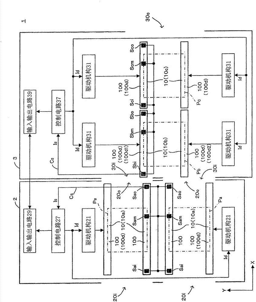
[0020] figure 1 It is a figure which schematically shows an example of the substrate processing line concerning 1st Embodiment of this invention. In this figure and the figures shown below, the XY orthogonal coordinate axes which set the board|substrate conveyance direction as the X-axis direction, and the direction orthogonal to the X-axis direction as the Y-axis direction are shown suitably. In this substrate processing line 1, a plurality of (two) substrate processing apparatuses 2 and 3 (a plurality of processing apparatuses) are arranged (arranged) in sequence along the substrate conveying direction X, and the substrate A is conveyed along the substrate conveying direction X ( Figure 4 ), and the substrate A is subjected to specified processing in each of the substrate processing apparatuses 2 and 3 .

[0021] In the substrate processing line 1, the substrate processing apparatus 2 (another processing apparatus, that is, the second processing apparatus) arranged on the ...

no. 2 approach >

[0070] Figure 7 It is a figure which schematically shows an example of the substrate processing line concerning 2nd Embodiment of this invention. The substrate processing line 1 of the second embodiment differs from the substrate processing line 1 of the first embodiment in that the arrangement of the substrate processing apparatuses 2 and 3 is reversed from that of the first embodiment. Therefore, the detailed structure of each of the substrate processing apparatuses 2 and 3 is the same as that described above in the first embodiment, and description thereof will be appropriately omitted here.

[0071] In the substrate processing line 1 of the second embodiment, two substrate processing apparatuses 3 and 2 are arranged sequentially along the substrate conveyance direction X, and the substrate A is conveyed along the substrate conveyance direction X, and the substrate A is processed in each of the substrate processing apparatuses 3 and 2 . In such a substrate processing lin...


PUM


Abstract

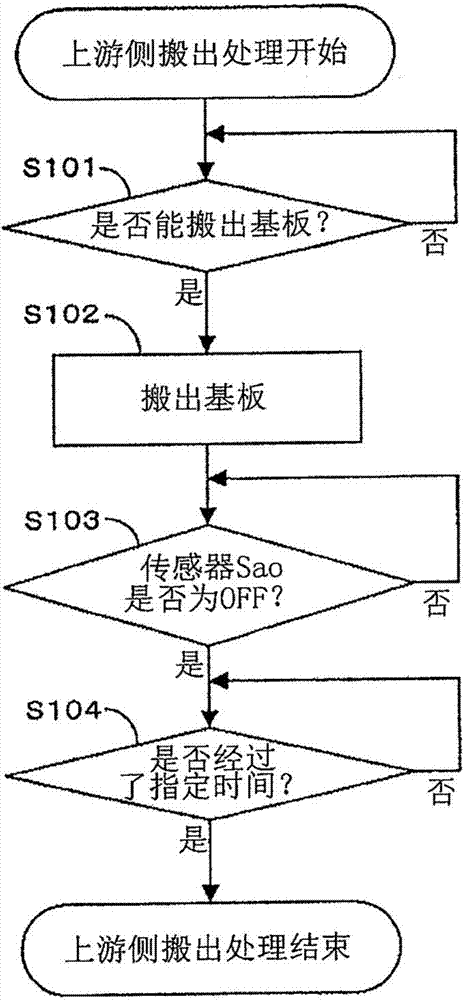
The invention relates to a substrate processing line and a substrate processing method. The substrate processing line comprises multiple processing devices which have conveying belts supporting substrates and conveying the substrates along a substrate conveying direction. One of the processing devices is provided with movable conveying belts which are taken as the conveying belts and are capable of moving freely along the intersection direction that the movable conveying belts are intersected with the substrate conveying direction. The one processing device and another processing device adjacent to the one processing device are internally provided with one position detecting part and another position detecting part for detecting the positions of the substrates. A controlling part controlling the moving of the movable conveying belts determines a result of the execution state of a substrate hand-over motion that the substrates are handed over between the movable conveying belts of the one processing device and the conveying belts of the another processing device according to detection results of the one position detecting part and the another position detecting part, and then controls the moving of the movable conveying belts. In this way, the moving of the movable conveying belts in an improper time period can be inhibited.

Description

technical field [0001] The present invention relates to a substrate processing technology in which a plurality of processing devices equipped with conveyor belts for supporting and transporting substrates are arranged in a row, substrates are transferred between the conveyor belts of adjacent processing devices, and substrates are processed in each processing device. to process. Background technique [0002] Japanese Patent Laid-Open Publication No. 2010-087136 (patent document) discloses a substrate processing line (the component mounting line of the patent document). Arrangement, transfer of boards between board input machine and component mounter and processing of boards. Specifically, the board feeding machine performs processing of feeding a board into a component mounting machine located downstream in the board conveying direction, and the component mounting machine performs processing of mounting components on a board fed from an upstream side in the board conveying ...

Claims


Application Information

Patent Timeline
IPC IPC(8): B65G37/00B65G47/52B65G43/08
CPCH05K1/0266H05K13/0015H05K13/0061H05K13/0417
Inventor 西村启二春日大介
Owner YAMAHA MOTOR CO LTD
Learn More