
Autonomous Shut-Off Valve System

a valve system and autonomous technology, applied in the field of valve systems, can solve the problems of affecting the operation of the valve system, affecting the operation of the valve, and the operation of the device is prone to failure, so as to reduce the exposure of workers and reduce the amount of maintenance or attendan

Inactive Publication Date: 2009-05-21
MATHER SAM
View PDF14 Cites 53 Cited by
  • Summary
  • Abstract
  • Description
  • Claims
  • Application Information

AI Technical Summary

Benefits of technology

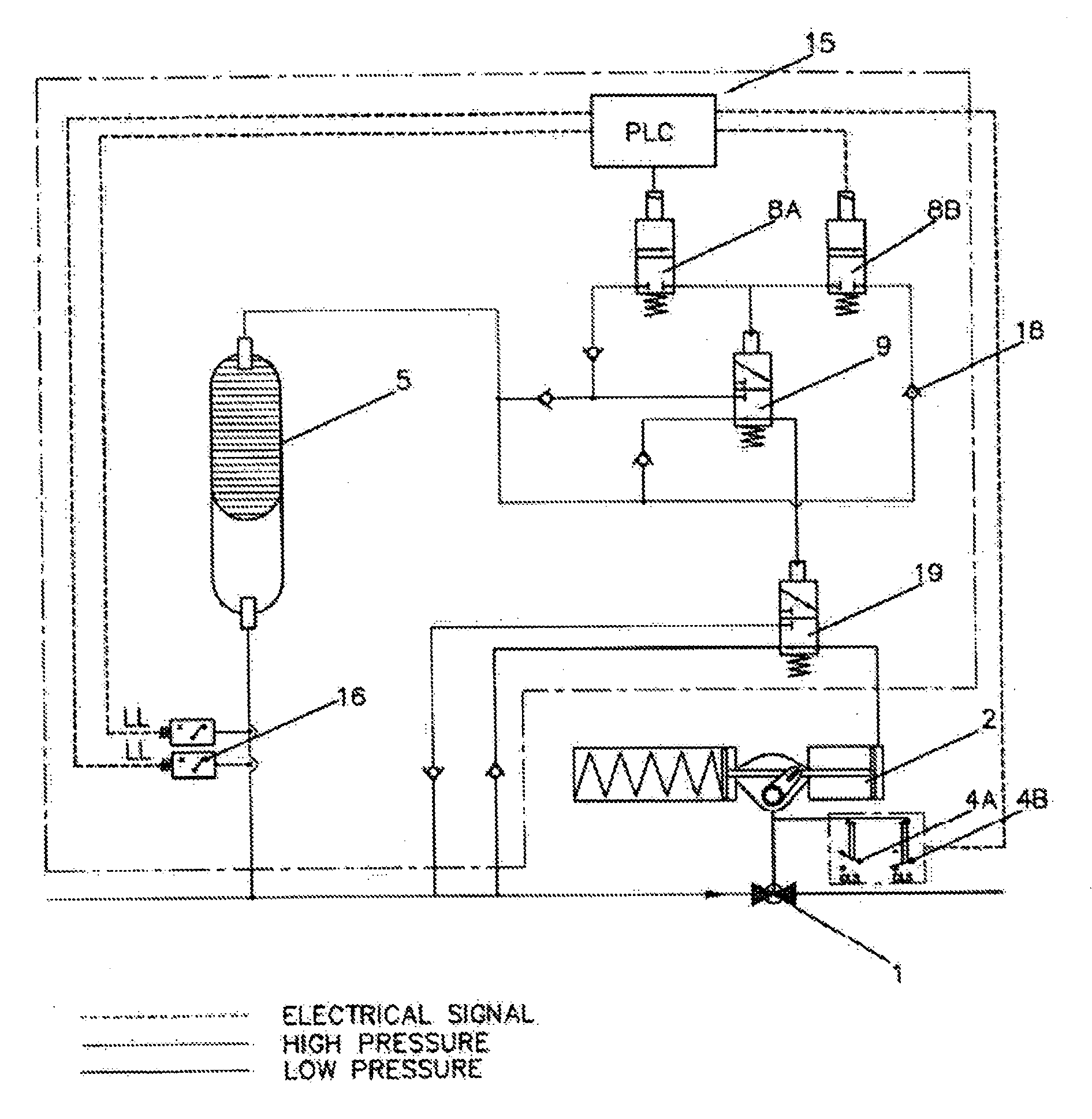
[0015]The invention provides a simple means of switching on and off a shut-off valve in a pipeline with no requirement to vent fluids to atmosphere. Whereas the prior art devices that do not vent to atmosphere require significant power or complex controls for their operation, the present invention requires only a very low power battery as the only power drawn is for the operation of solenoids to control the direction of flow of process fluid through the apparatus. It is the process fluid that provides the power to open and close the shut-off valve and that fluid may be an incompressible fluid such as oil. Low power batteries are readily available and are claimed by their manufacturers to have a lifespan of at least seven years. The apparatus of the present invention requires very little maintenance or attendance, which in the environment where it would be deployed is extremely advantageous, both in terms of financial cost and reducing the exposure of workers to potential danger.

Problems solved by technology

Such an environment is particularly hostile.
The performance of such stations in terms of reliability, the requirement for maintenance and the requirement for services, such as power pose considerable problems for operators.
Whilst power can be generated by solar elements or wind turbines, such devices are apt to fail in hostile environments requiring manpower to be deployed at great expense and danger.
In systems transporting gas (compressible fluid) it is known to use the process fluid to operate an actuator causing shut-off of a valve when downstream failure is detected.
However, such devices require venting to atmosphere of at least an amount of process fluid, which by its very nature involves pollution and can create a hazard.
The known devices either vent process fluid to atmosphere or require significant power or complex controls to open valves after closure due to pipeline failure or controlled shut down.

Method used


Image

  • Autonomous Shut-Off Valve System
  • Autonomous Shut-Off Valve System
  • Autonomous Shut-Off Valve System

Examples


Embodiment Construction

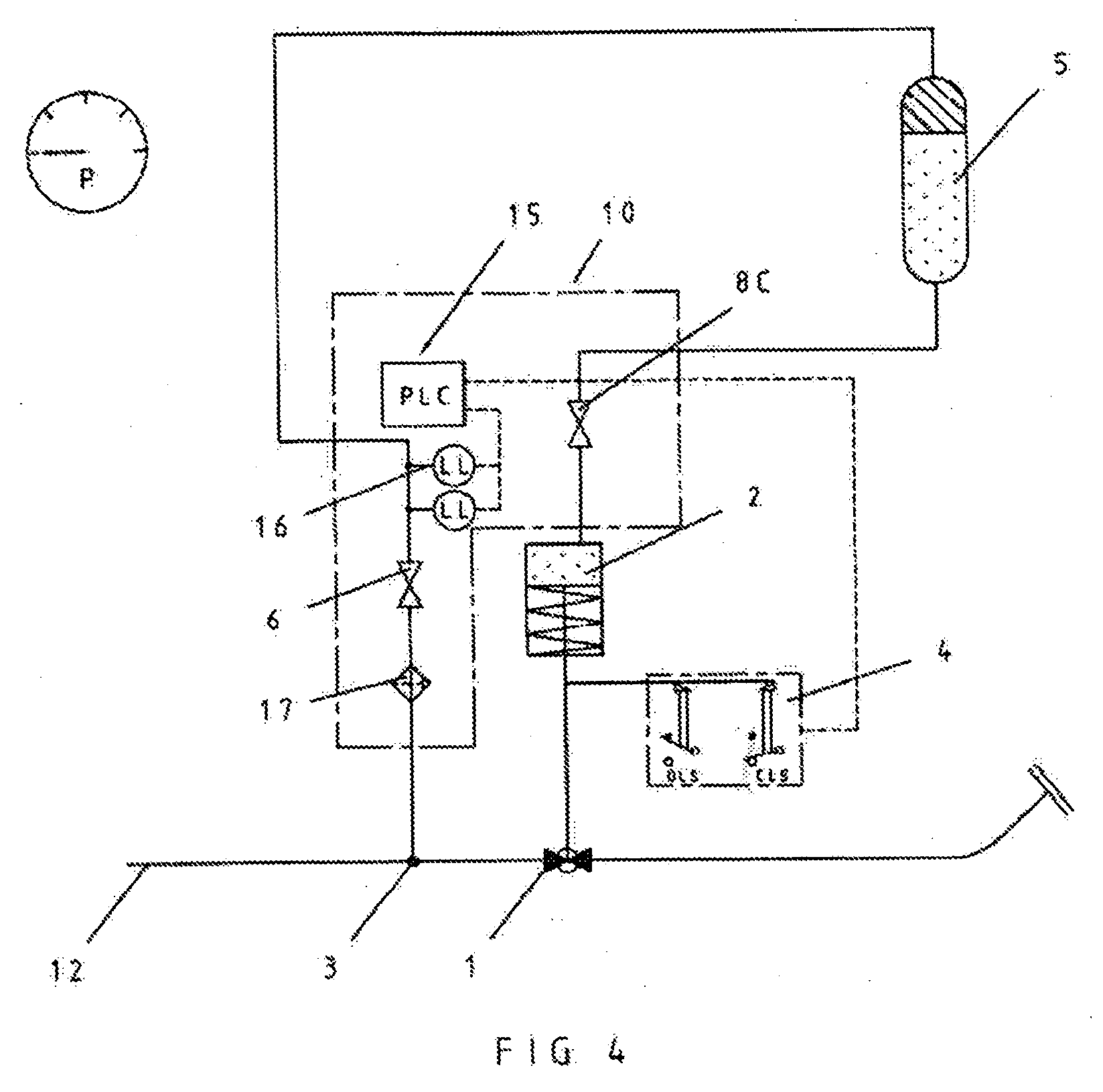
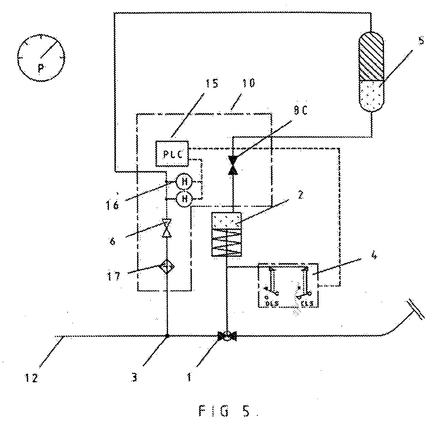
[0035]Referring now to FIG. 1, there is illustrated apparatus for transferring oil from the sub-surface to a surface installation. The apparatus comprises an autonomous shut-off valve system including a control system 10, a pipeline 12, for example a sub-sea or over-land pipeline, and a process pump 11 which pumps fluid through the pipeline 12, for example crude oil. Downstream the pipeline 12 connects to a flexible riser pipe 13, the downstream end of which connects to a surface installation 14. In use a tanker draws up to the surface installation, makes a fluid connection therewith, and the pump 11 is commanded to pump fluid which fills the tanker. The flexible riser pipe is one of the most likely points of failure of the pipeline.

[0036]The autonomous shut off valve system is located between the pump 11 and the surface installation 14 and comprises a pipeline ball valve 1 located in the main pipeline 12 and a pressure tapping 3 into the main pipeline 12. The pump 11 will usually b...


PUM


Abstract

A pipeline (12) for the transportation of a process fluid comprises an autonomous shut-off valve system comprises a shut-off valve (1) including a fluid powered valve actuator (2) moveable between a closed and an open position by means of pressure generated by the process fluid, a pressure tapping (3) in the pipeline upstream of the shut-off valve, a fluid connection to the pressure tapping arranged to deliver process fluid to power opening of the said shut-off valve, at least one pressure sensor (16) arranged in a hydraulic line extending from the pressure tapping, at least one control valve (8A, 8B, 8C) operable to permit or prevent flow of pressurised fluid to the shut-off valve actuator; and a controller (15) arranged to open and close the control valve. The control valve is commanded to open and close when pressure thresholds are reached, the pressure thresholds being detected by the pressure sensor and the control valve being commanded to close by the controller.

Description

FIELD OF THE INVENTION[0001]This invention relates to a valve system for controlling the flow of fluids, and more particularly to a valve for controlling the flow of oil through a pipeline.BACKGROUND OF THE INVENTION[0002]In certain industries, for example those involving oil and gas, water or chemical manufacture, there is a requirement to control the flow of fluids through pipelines remotely. In the off-shore oil and gas industry oil / gas is extracted from beneath the sea bed by a production installation, the oil / gas potentially being transported to an oil refinery by means of a tanker vessel. Typically, a tanker may be charged via an unmanned installation at sea. Such an environment is particularly hostile. Unmanned stations are used in many remote and / or hostile environments. The performance of such stations in terms of reliability, the requirement for maintenance and the requirement for services, such as power pose considerable problems for operators. Whilst power can be generat...

Claims


Application Information

Patent Timeline
Patent Type & Authority Applications(United States)
IPC IPC(8): G05D7/06F16K17/20F16K17/22F16K31/128F16K17/00
CPCE21B41/0021E21B43/00F15B13/0426F15B2211/6336F15B2211/329F15B2211/6309F15B2211/212Y10T137/7768Y10T137/3056Y10T137/0379F16K31/12
Inventor MATHER, SAM
Owner MATHER SAM
Learn More