
Image forming apparatus and analysis method

a technology of image forming apparatus and analysis method, which is applied in the direction of image enhancement, digital output to print units, instruments, etc., can solve the problems of difficulty in performing comparison with print jobs under normal conditions, difficulty in correctly obtaining packets if a dedicated device, and problems in the technique of the related art described abov

Inactive Publication Date: 2009-05-07
CANON KK
View PDF4 Cites 9 Cited by
  • Summary
  • Abstract
  • Description
  • Claims
  • Application Information

AI Technical Summary

Benefits of technology

The present invention allows for effective analysis of communication failures by obtaining all necessary packets. An image forming apparatus is used to process jobs, and when an error occurs, the system detects and stores failed packets. The system then compares the tendency of occurrence of packets obtained by executing the application with the tendency of occurrence of stored failed packets. The system detects types of packets that differ from the failed packets and are stored. This technology helps to identify the root cause of communication failures and improve network performance.

Problems solved by technology

Thus, it is possible to obtain packets even in an environment where it is difficult to correctly obtain packets if a dedicated device is connected, such as an environment where a switching hub is installed.
However, the technique of the related art described above has problems as follows.
A first problem is that due to the filtering, it is difficult to perform comparison with print jobs under normal conditions.
As in the technique of the related art described above, as a result of filtering performed for every print job, a fault analyzer can only obtain packets associated with a print job in which a fault has occurred.
Therefore, if a communication failure that can cause a fault is found in the obtained packets, it is difficult to determine whether or not the communication failure is the cause of the fault.
For example, in a case where an event that can cause a fault, such as retransmission of a packet or transmission retry, has occurred in an obtained print job, if this event also occurs in a print job that can correctly be printed, the probability that the event causes the fault may be low.
In the technique of the related art, however, it is necessary to investigate all communication failures detected in packets, and a large load is imposed on the analyzer.
Another problem is that although the number of packets can be relatively reduced by performing filtering, if the absolutely number of packets (amount of data) is large, a long time is required for the analysis.
With the recent increase in the complexity and functionality of network applications, the size of data delivered over networks has also increased.
Since recent network printers may receive a print job larger than 1 gigabyte in data size, a large amount of time is required for an analyzer to analyze packet data of 1 gigabyte.

Method used


Image

  • Image forming apparatus and analysis method
  • Image forming apparatus and analysis method
  • Image forming apparatus and analysis method

Examples


first embodiment

[0029]A first embodiment of the present invention will be described hereinafter with reference to the drawings.

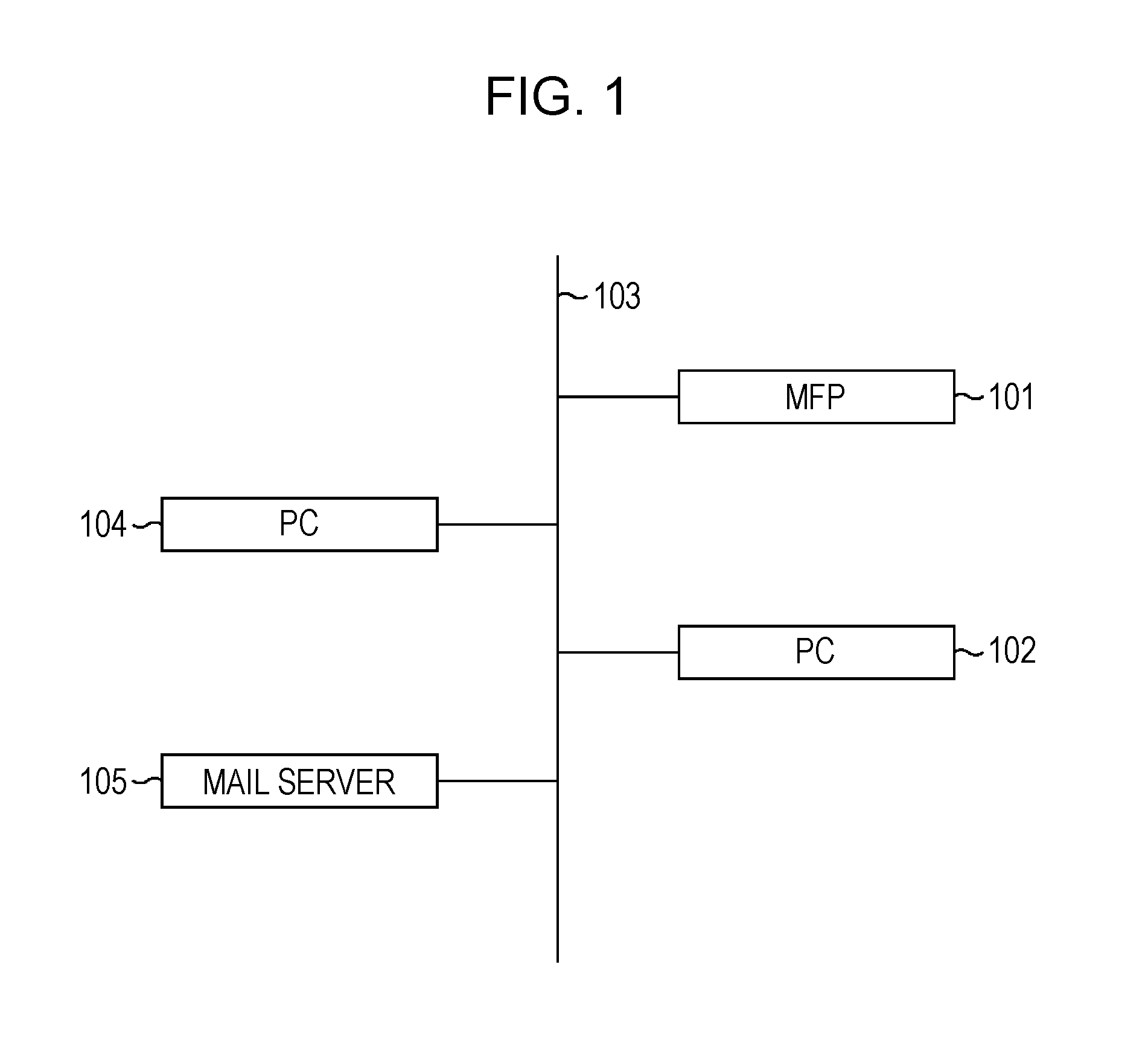
[0030]FIG. 1 is a block diagram showing an example structure of a network system.

[0031]A LAN 103 is a user environment network and may be, for example, an Ethernet (registered trademark in Japan) network. Nodes each having a plurality of network interfaces, which will be described below, are connected to the LAN 103.

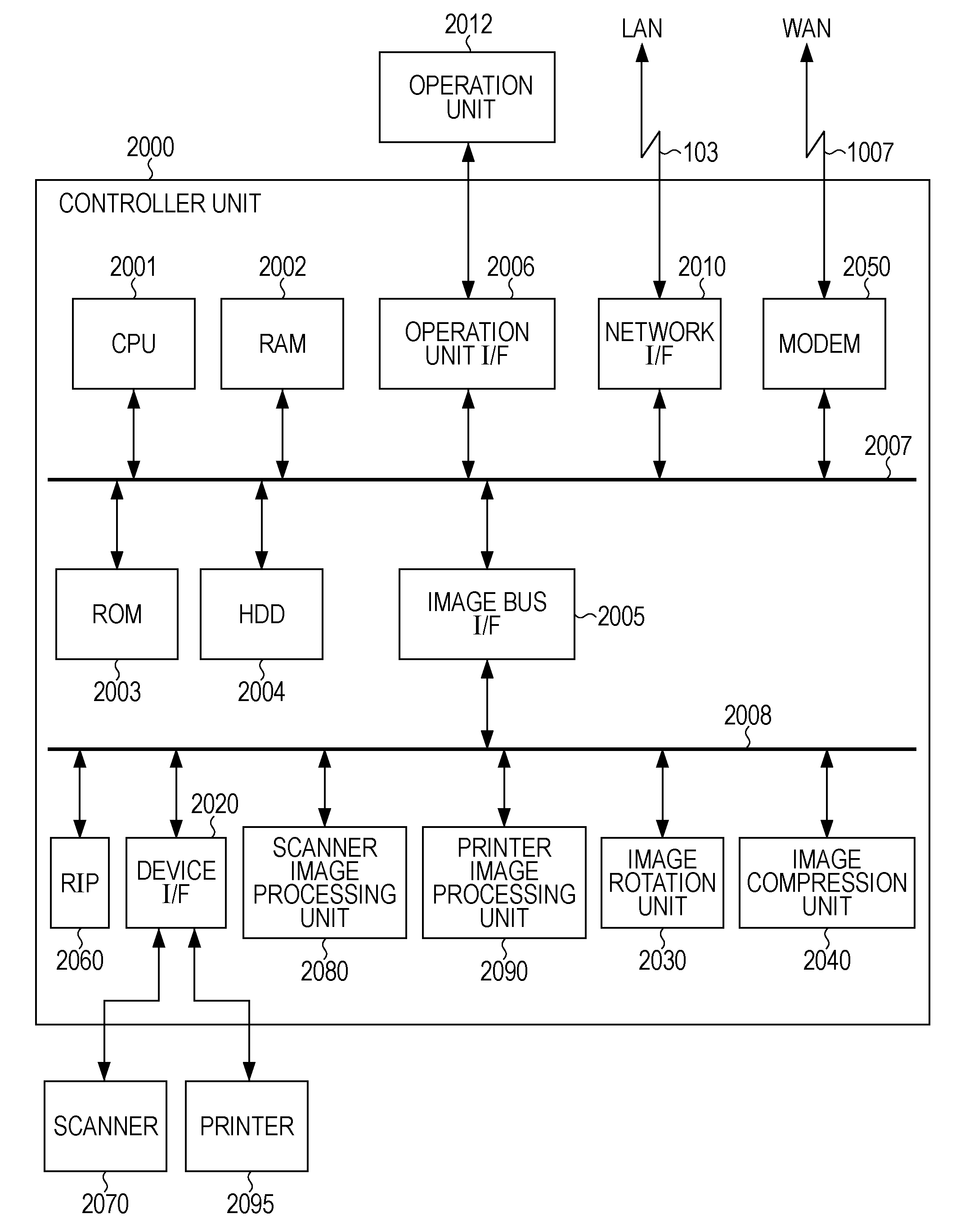
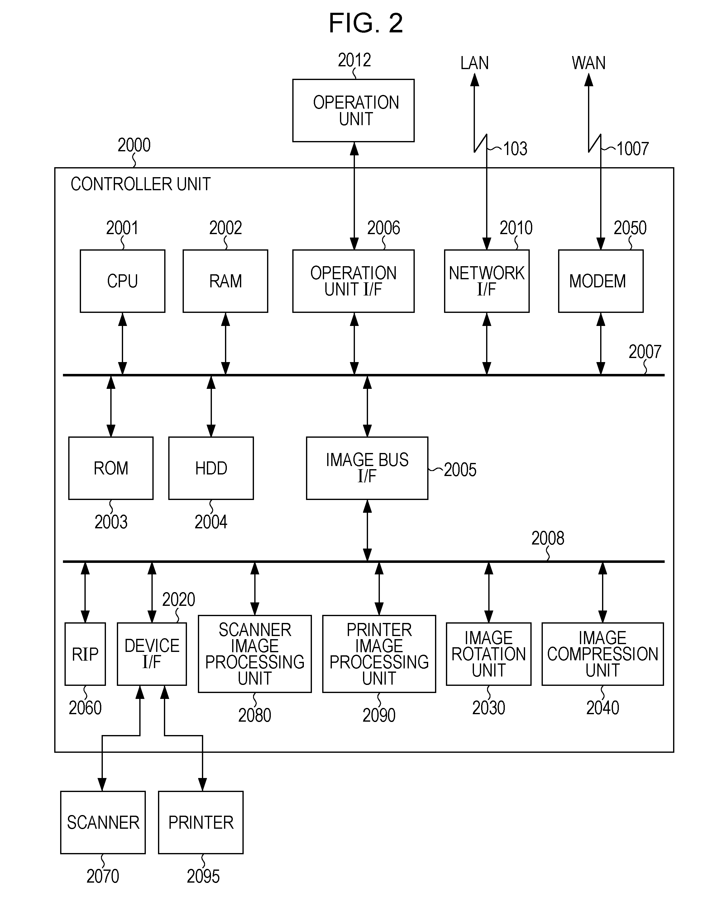
[0032]A multi function peripheral (MFP) 101 is a multifunction device. The hardware of the MFP 101 will be described below in detail with reference to FIG. 2.

[0033]Personal computers (PCs) 102 and 104 are general-purpose PCs. The hardware of each of the PCs 102 and 104 mainly includes a central processing unit (CPU) serving as a central operation device; a storage device including a random access memory (RAM), a read only memory (ROM), and a hard disk drive (HDD); an external storage device including a compact disc read only memory (CD-ROM) drive; and an externa...

second embodiment

[0112]A second embodiment of the present invention will now be described. In the first embodiment described above, an example of an application in which an error has occurred has been described in the context of the PDL unit 402. In the present embodiment, on the other hand, the occurrence of an error in the data transmission application 404 will be described by way of example. Therefore, in the present embodiment, an error has occurred in an application different from that in the first embodiment, and the same or similar portions in the present embodiment as or to those in the first embodiment described above are assigned the reference numerals shown in FIGS. 1 to 13 and will not be discussed in detail herein.

[0113]FIG. 14 is a diagram showing an example of errors that can occur in the data transmission application 404.

[0114]In FIG. 14, a “content of data transmission application error” field 1210 shows examples of errors that have occurred when the data transmission application 40...

third embodiment

[0118]A third embodiment of the present invention will now be described. In the first embodiment described above, in step S802 of FIG. 10, a comparison in terms of the number of packets is performed to determine whether or not a communication failure log is available for comparison. In the present embodiment, on the other hand, other conditions such as an elapsed time, as well as the number of packets, are also taken into consideration to determine whether or not a communication failure log is available for comparison. Therefore, the present embodiment is mainly different from the first and second embodiments described above in that an operation different from that in the first and second embodiments is performed to determine whether or not a communication failure log is available for comparison. Thus, in the present embodiment, the same or similar portions as or to those of the first and second embodiments described above are assigned the reference numerals shown in FIGS. 1 to 14 a...


PUM


Abstract

A sufficient number of packets necessary for analysis of a fault in a network communication apparatus are obtained. A multi function peripheral (MFP) temporarily stores received packets as a file for every print job, and stores communication failure information as a log (communication failure log). The MFP deletes data in which no error has occurred in an application among the stored files. Then, in a case where an error has occurred during processing of a certain print job, the MFP stores received packets in a storage device, and compares a communication failure in the job packet in which the error has occurred with a communication failure in packets associated with all the received print jobs. As a result of the comparison, the MFP extracts a communication failure in only the job packet in which the error has occurred, and creates a log so that the extracted result can be identified.

Description

BACKGROUND OF THE INVENTION[0001]1. Field of the Invention[0002]The present invention relates to an image forming apparatus and an analysis method, and more specifically, to a technique for performing analysis of errors that have occurred in apparatuses using packets.[0003]2. Description of the Related Art[0004]Techniques have been developed in which when a fault has occurred in a network communication device, packets delivered over networks (communication lines) are extracted to investigate the cause of the fault. In a typical example of such techniques, a dedicated device used to obtain packets is connected to a line concentrator such as a hub to extract packets delivered over a local area network (LAN). The content of data of packets transmitted and received by a target network communication device to be investigated is determined using analysis of the extracted packets to specify a portion that has received unacceptable data or a portion where a response delay to a received pack...

Claims


Application Information

Patent Timeline
Patent Type & Authority Applications(United States)
IPC IPC(8): G06F11/30
CPCH04L41/0677H04L43/16H04L43/0817H04L43/0811
Inventor SHOUNO, HIROKI
Owner CANON KK
Learn More