
Minimization of surface reflectivity variations

a surface reflectivity and surface technology, applied in metal working equipment, manufacturing tools, welding/soldering/cutting articles, etc., can solve the problems of affecting the uniformity of light absorption of the surface, affecting the uniformity of light absorption, and affecting the uniformity of the surface of the processed or patterned wafer, so as to minimize the maximum surface reflectivity and minimize the surface reflectivity. the effect of the surface reflectivity

Inactive Publication Date: 2009-05-07
ULTRATECH INT INC
View PDF8 Cites 24 Cited by
  • Summary
  • Abstract
  • Description
  • Claims
  • Application Information

AI Technical Summary

Benefits of technology

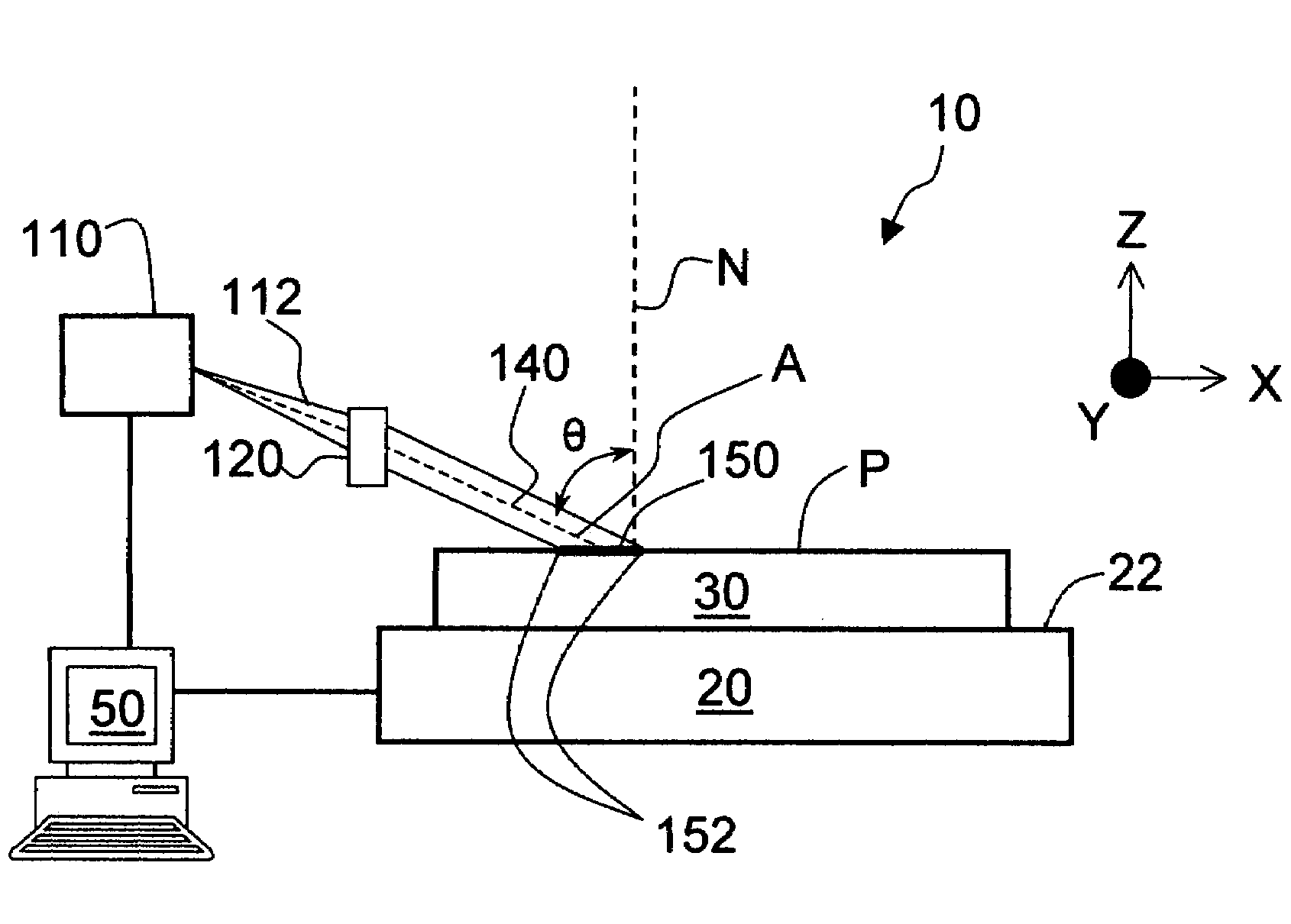
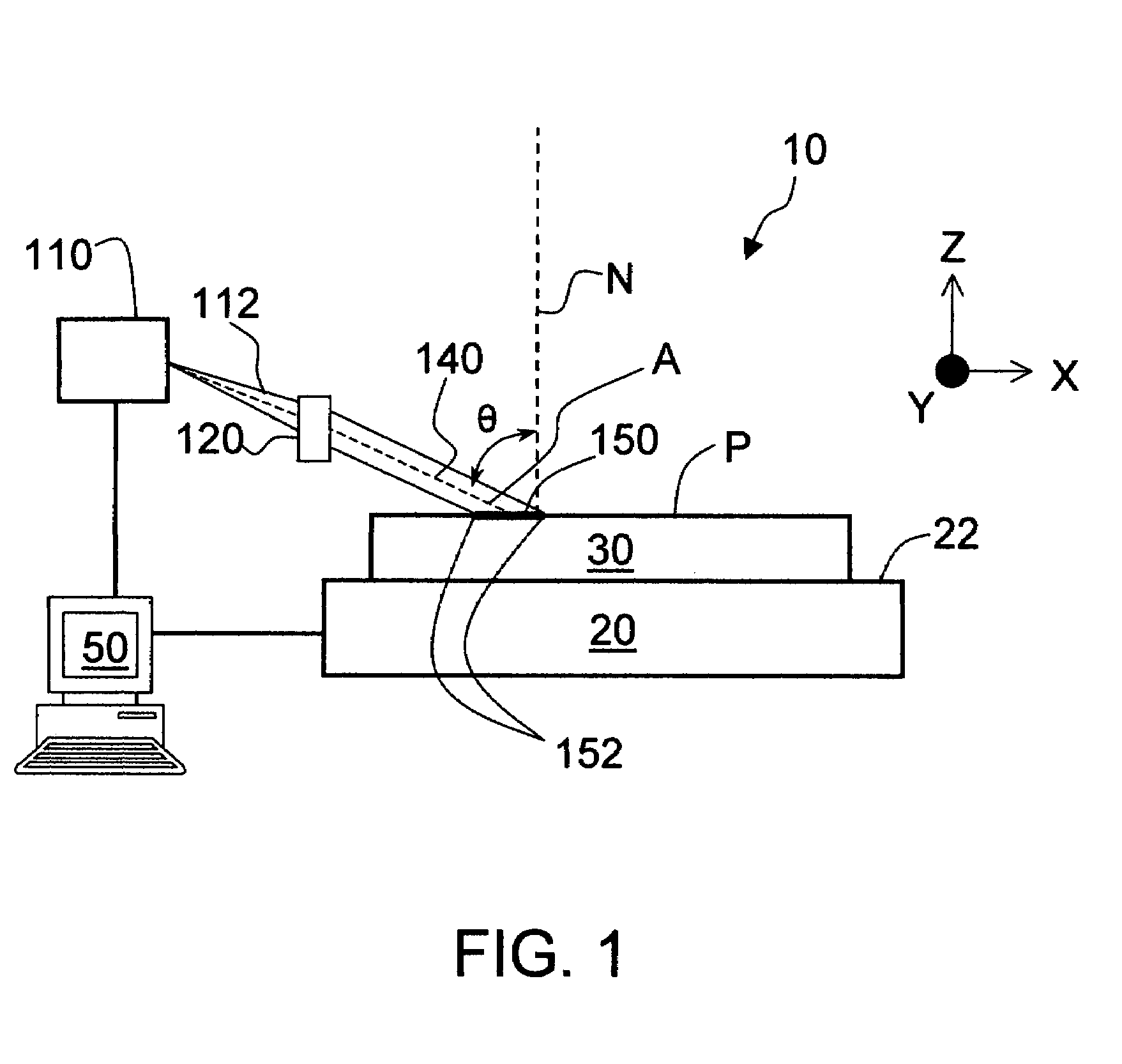
[0014]In a first aspect, the invention provides an apparatus for processing a surface of a substrate having a surface normal and a surface pattern. The apparatus may, for example, include a radiation source, a stage, a relay, an alignment system, and a controller. The radiation source emits a photonic beam. The stage supports and moves the substrate relative to the beam. The relay directs the photonic beam from the radiation source toward the substrate at an incidence angle relative to the surface normal. The alignment system positions the substrate on the stage so the pattern is disposed at an orientation angle relative to the beam. The controller is operably coupled to the radiation source, relay, alignment system and / or stage and provides relative scanning movement between the stage and the beam. The controller maintains the orientation angle and incidence angle at values selected to substantially minimize substrate surface reflectivity variations and / or minimize the maximum substrate surface reflectivity during scanning.
[0018]In a further aspect, the invention provides an apparatus for processing a surface of a substrate, e.g., a substrate having a surface pattern that exhibits directionally and / or orientationally different reflectivities relative to radiation of a selected wavelength and polarization. The apparatus includes a radiation source, a relay, a stage, and a controller. The radiation source emits a photonic beam of the selected wavelength and polarization. The relay directs the photonic beam from the radiation source toward the substrate an incidence angle relative to the substrate surface normal. The stage supports the substrate at an orientation angle relative to the beam. The controller is operably coupled to the radiation source, relay, and / or stage. In operation, the controller provides relative scanning movement between the stage and the beam while maintaining the orientation angle and incidence angle at values selected to minimize substantially substrate surface reflectivity variations and / or maximum substrate surface reflectivity during scanning.

Problems solved by technology

Wafers with nonuniform surfaces (e.g., processed or patterned wafers), however, represent a particularly difficult challenge.
Items such as devices and conductive pathways on wafer surfaces can hinder uniform light absorption.
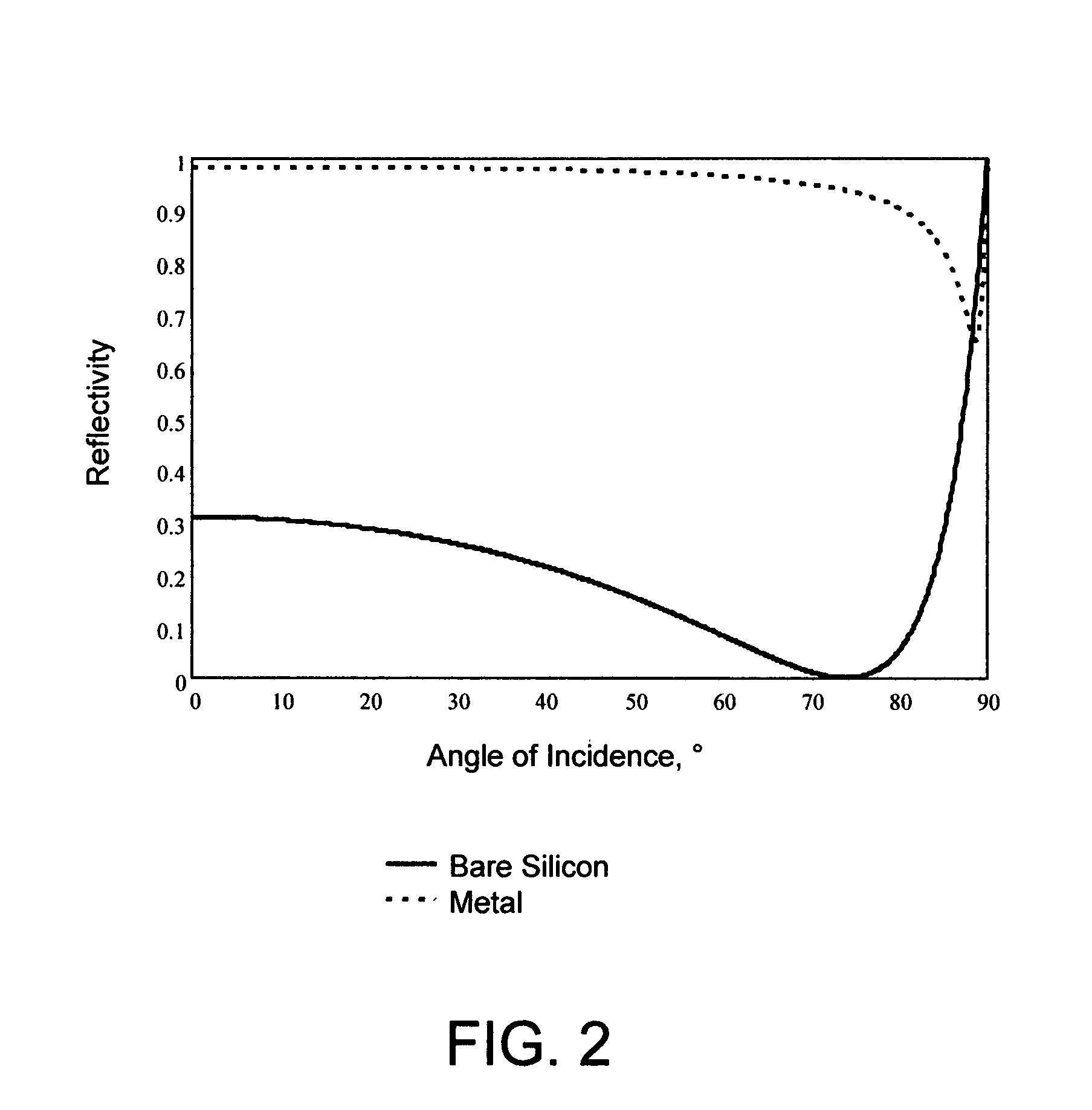
Thus, regardless whether flash lamp or laser technologies are used, reflectivity differences may cause the energy source to heat different portions of a nonuniform wafer surface differently.

Method used


Image

  • Minimization of surface reflectivity variations
  • Minimization of surface reflectivity variations
  • Minimization of surface reflectivity variations

Examples


Embodiment Construction

Definitions and Overview

[0036]Before describing the present invention in detail, it is to be understood that this invention, unless otherwise noted, is not limited to specific substrates, lasers, or materials, all of which may vary. It is also to be understood that the terminology used herein is for the purpose of describing particular embodiments only, and is not intended to be limiting.

[0037]It must be noted that, as used in this specification and the appended claims, the singular forms “a”, “an” and “the” include both singular and plural referents unless the context clearly dictates otherwise. Thus, for example, reference to “a beam” includes a plurality of beams as well as a single beam, reference to “a wavelength” includes a range or plurality of wavelengths as well as a single wavelength, and the like.

[0038]In describing and claiming the present invention, the following terminology will be used in accordance with the following definitions.

[0039]The terms “Brewster's angle” or ...


PUM

PropertyMeasurementUnit
incidence angleaaaaaaaaaa
Brewster's angleaaaaaaaaaa
peak temperatureaaaaaaaaaa

Abstract

Apparatuses and methods are provided for processing a surface of a substrate. The substrate may have a surface pattern that exhibits directionally and / or orientationally different reflectivities relative to radiation of a selected wavelength and polarization. The apparatus may include a radiation source that emits a photonic beam of the selected wavelength and polarization directed toward the surface at orientation angle and incidence angle selected to substantially minimize substrate surface reflectivity variations and / or minimize the maximum substrate surface reflectivity during scanning. Also provided are methods and apparatuses for selecting an optimal orientation and / or incidence angle for processing a surface of a substrate.

Description

BACKGROUND OF THE INVENTION[0001]1. Field of Invention[0002]The invention relates generally to methods and apparatuses for processing a surface of a substrate using a photonic beam. More specifically, the invention relates to methods and apparatuses that carry out such processing in a manner that accounts for and / or minimizes reflectivity variations and / or the maximum surface reflectivity of a surface of a substrate relative to the photonic beam.[0003]2. Description of Related Art[0004]Fabrication of semiconductor-based microelectronic devices such as processors, memories and other integrated circuits (ICs) require thermal processes. For example, the source / drain portions of transistors may be formed by exposing regions of a silicon wafer substrate to accelerated dopants containing boron, phosphorous or arsenic atoms. After implantation, the interstitial dopants are electrically inactive and require activation. Activation may be achieved by heating the entirety or a portion of the s...

Claims


Application Information

Patent Timeline
Patent Type & Authority Applications(United States)
IPC IPC(8): B23K26/08B23K26/02
CPCB23K26/0066B23K26/0738B23K26/0853B23K26/0081H01L21/268H01L21/28044B23K2201/40B23K26/352B23K26/354B23K2101/40B23K2103/56
Inventor HAWRYLUK, ANDREW M.
Owner ULTRATECH INT INC
Learn More