
Expandable reverse shoulder trial

a trial and expansion technology, applied in the field of expandable reverse shoulder trial, can solve the problems of dislocation of joints, decrease in size and cost of overall instrument sets, etc., and achieve the effects of reducing distance, increasing thickness, and facilitating trialing

Active Publication Date: 2009-04-16
HOWMEDICA OSTEONICS CORP
View PDF68 Cites 28 Cited by
  • Summary
  • Abstract
  • Description
  • Claims
  • Application Information

AI Technical Summary

Benefits of technology

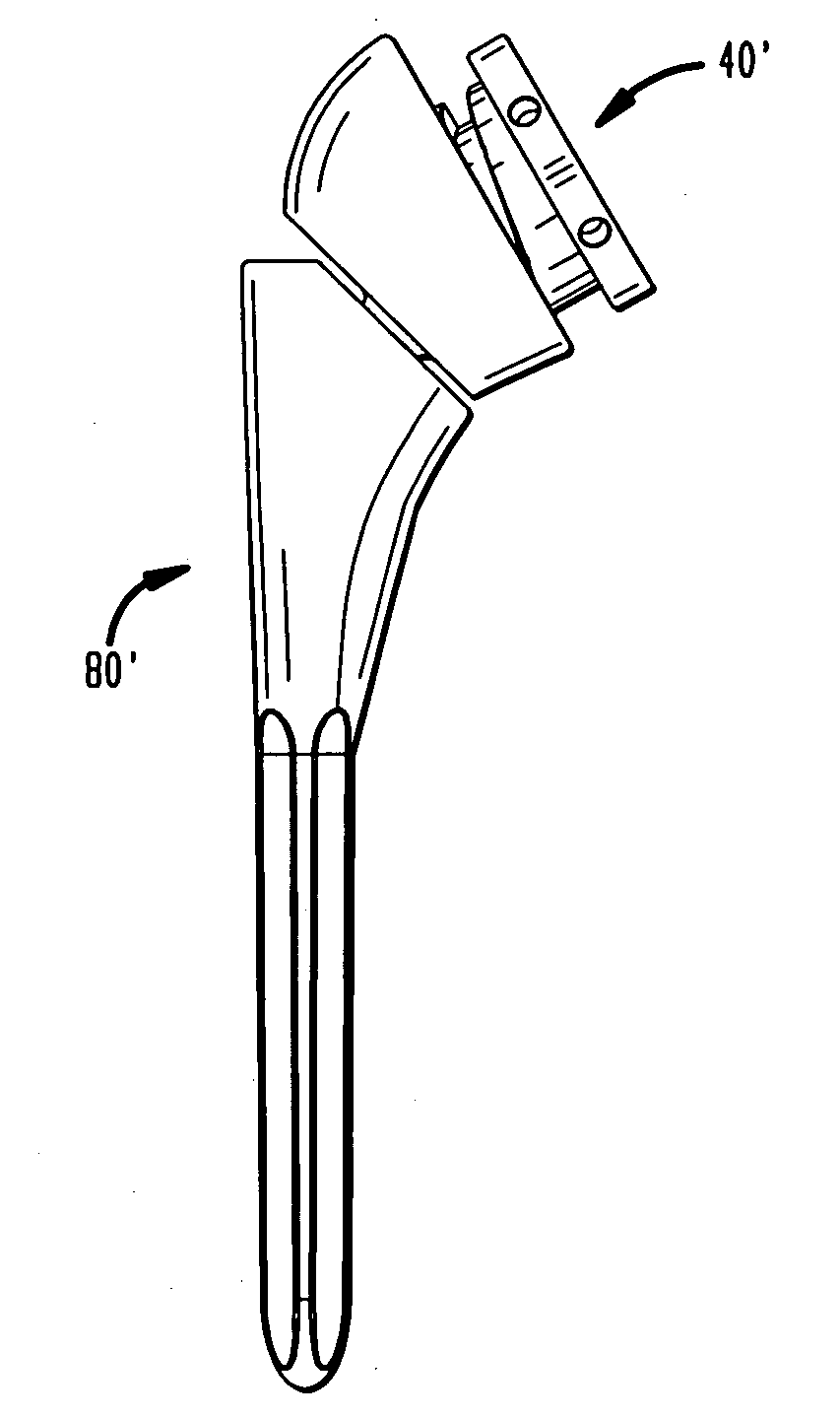
[0007]The present invention greatly eases the reduction and dislocation of a shoulder joint during trialing because the surgeon may custom fit a trial to a patient after the joint has been reduced. This will greatly decrease the patient's exposure to intraoperative soft or hard tissue injuries related to extreme forces required to reduce and dislocate the joint. Moreover, the preferred one-step trialing approach of the present invention will also decrease surgical time, which is healthier for the patient and more efficient for the surgeon and hospital. Preferably, the expandable trial also decreases the size and cost of the overall instrument set, since only one trial per glenosphere diameter is generally required.
[0008]A main distinguishing characteristic of the adjustable trial from prior art devices is the fact that an insert may be first inserted into a humeral cup and then rotated into a collapsed or neutral position. This preferably allows the surgeon to easily reduce the joint. The trial, including the insert and humeral cup may then be expanded into a second position wherein optimal deltoid tension is preferably achieved. Here, the trial is calibrated such that the surgeon can determine which liner thickness corresponds to the dialed position on the trial.
[0009]Following ROM and joint stability analysis, the surgeon can easily collapse the trial back to the neutral position and simply dislocate the joint. The trial may also be expanded prior to joint reduction and collapsed prior to joint dislocation repeatedly, depending on surgeon preference.
[0010]The purpose of the present invention is to allow the surgeon to reduce the reverse shoulder trial and surrounding soft tissues into a relaxed state and / or dislocate a reduced shoulder joint while in a relaxed state. This will greatly ease the reduction of the joint. Once reduced, the surgeon may then “dial in” the appropriate liner thickness to achieve proper soft tissue tension. The trial is preferably designed to expand in discreet increments which correspond to liner prostheses that are available in multiple thicknesses. After a liner prosthesis is selected, it is then implanted with a humeral cup prosthesis.
[0033]In one aspect of a method of the present invention, the insert may be rotated in the first direction approximately 60° to reduce the distance between the proximal end of the humeral cup and the proximal end of the insert approximately 2 mm. Preferably, the insert includes an incremental stopping portion every 60° along the guide portion or cam-track of the shaft portion of the insert. As the insert is rotated in either a first or second direction the guide pin of the humeral cup may engage an incremental stopping portion of the insert. This may stop the insert from further rotation until a force great enough to overcome the friction between the guide pin and the incremental stopping portion is produced.
[0034]Generally, the present invention is an expandable reverse shoulder trial for RSA. In one aspect of the present invention, the trial is designed to take the place of a kit of trials and to provide the surgeon with greater intraoperative flexibility and ease of trialing during RSA. Prior art devices include trials of increasing thicknesses in “kit” form.

Problems solved by technology

Preferably, the expandable trial also decreases the size and cost of the overall instrument set, since only one trial per glenosphere diameter is generally required.
Following ROM and joint stability analysis, the surgeon can easily collapse the trial back to the neutral position and simply dislocate the joint.

Method used


Image

  • Expandable reverse shoulder trial
  • Expandable reverse shoulder trial
  • Expandable reverse shoulder trial

Examples


Embodiment Construction

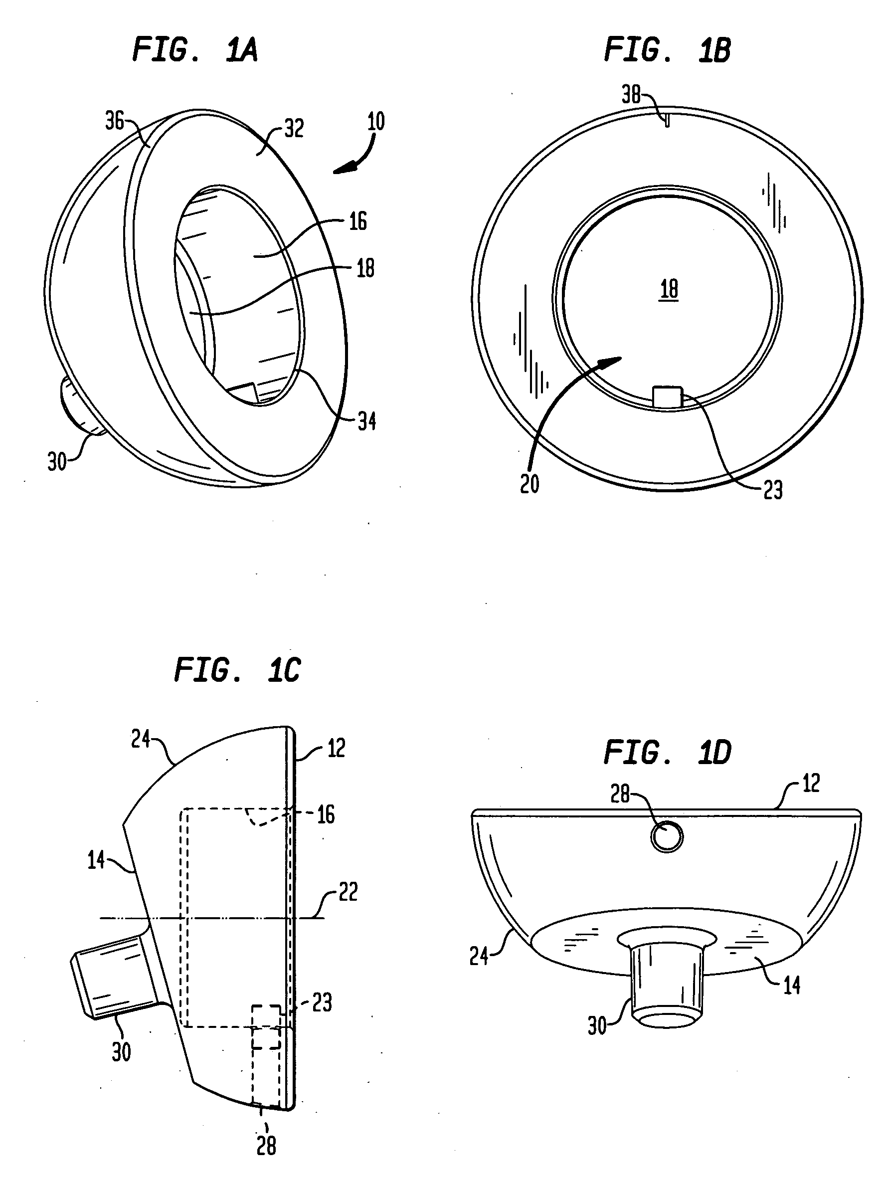
[0080]Referring to FIGS. 1A-1D, there is shown an embodiment of a humeral cup of the present invention designated generally by reference numeral 10. As shown in those figures, cup 10 includes a proximal end 12 and a distal end 14. Cup 10 preferably further includes a circular wall 16 and a base 18 defining a recess 20. Recess 20 defines a central axis 22 as shown in FIG. 1C. Preferably, a guide portion 23 protrudes from wall 16. Guide portion 23 is preferably configured as a pin.

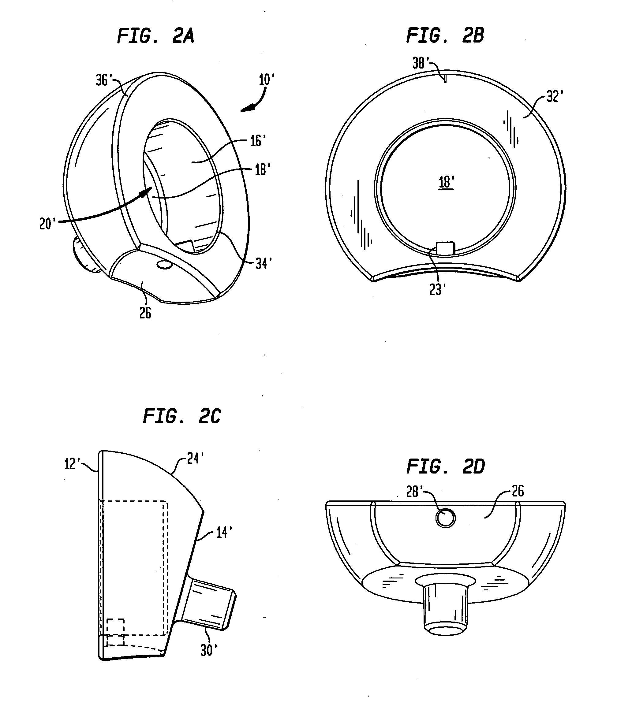
[0081]In the preferred embodiment, proximal end 12 and distal end 14 of cup 10 are not coplanar. Between distal end surface 14 and proximal end surface 12 is a hemispherical outer surface 24. In an alternative embodiment, as shown in FIGS. 2A-2D, a cup 10′ further includes a concave surface 26 located between a proximal end surface 12′ and a distal end surface 14′. Surface 26 faces medially and is preferably configured to allow for greater articulation of cup 10′ with respect to a scapula bone after cup 10′ ...


PUM


Abstract

An expandable shoulder trial for a reverse shoulder system is described. The trial includes a rotatably adjustable insert housed within a humeral cup. The insert has a proximal end and a distal end, the proximal end having a concave recess therein adapted to receive a glenosphere prosthesis. The distal end of the insert includes a shaft, the shaft having a helical groove disposed on at least a portion thereof. A distal end of the humeral cup is inserted in a humeral stem. The humeral cup has a proximal end including a recess therein, the recess defined by a circular wall. A guide pin protrudes from the circular wall and is adapted to engage the helical groove of the shaft of the insert. The proximal end of the insert may rotate along an axis toward the proximal end of the humeral cup and along the same axis away from the proximal end of the humeral cup.

Description

FIELD OF THE TECHNOLOGY[0001]The present invention relates to an expandable reverse shoulder trial for reverse shoulder athroplasty (RSA), and in particular it relates to such a trial including an insert that rotatably engages a humeral cup.BACKGROUND OF THE INVENTION[0002]The successful outcome of RSA depends greatly on proper soft tissue tension. Since the rotator cuff is either absent or severely compromised and irreparable, the stability of the shoulder joint comes from significant deltoid tension holding the ball and socket joint together.[0003]Existing reverse shoulder systems require a surgeon to pick a trial liner and reduce the shoulder joint with that liner assembled into a humeral cup. If the correct liner is chosen, the soft tissue tension is significant, requiring the surgeon to apply extreme force to the humerus and surrounding soft tissues to reduce the joint. If no additional damage is done during this reduction process, the joint must then be dislocated to allow the...

Claims


Application Information

Patent Timeline
IPC IPC(8): A61F2/40
CPCA61F2/40A61F2250/0097A61F2/4684A61F2002/30331A61F2002/30332A61F2002/3042A61F2002/30507A61F2002/3055A61F2002/30553A61F2002/30594A61F2002/30617A61F2002/4022A61F2002/4037A61F2002/4044A61F2002/4085A61F2220/0025A61F2220/0033A61F2250/0007A61F2250/0008A61F2/4014
Inventor SPLIETH, ROY PHILIPLOREK, JAMES DAVIDKROLL, SHAWN MICHAEL
Owner HOWMEDICA OSTEONICS CORP
Learn More