
Axial Pullwire Tension Mechanism for Self-Expanding Stent

a tension mechanism and self-expanding technology, applied in the field of tension mechanism, can solve the problems of high cost, high risk, and high cost of thoracotomy, and achieve the effects of reducing the risk of extra surgery, and reducing the risk of surgery

Inactive Publication Date: 2009-04-16
WENG NING
View PDF26 Cites 176 Cited by
  • Summary
  • Abstract
  • Description
  • Claims
  • Application Information

AI Technical Summary

Benefits of technology

[0027]Said bus lines of all distal pull wires and proximal pull wires may merge, thereby allowing the stent to relax or tension almost symmetrically by pulling or pushing just one bus line that controls all distal and proximal pull wires.

Problems solved by technology

However, due to various uncertain elements, heart valves are vulnerable to acquired injuries and are subject to pathological complications, typically rheumatism and atherosclerosis.
The thoracotomy as mentioned above is plagued with prolonged surgical time consumption, sky-high costs, substantial physical trauma and great risks.
In addition, the metal-mechanical valve requires the patients to go through long-term anti-coagulation therapy, while extra surgeries are rife for patients using biological valves due to its limited lifespan.
The defects of the sheath tube are that: 1. current sheath tubes for the delivery system and the radially compressed stents are hard and are of poor bending flexure; 2. friction forces between the self-expanding stent and the sheath tube in the delivery system is too big for the accurate placement of the stent and that the retraction of the sheath tube tends to encounter great resistance when the self-expanding stent is highly compressed, which results in the displacement of the stent; 3. the laterally sealed thin sheath tube blocks the guide wire that is intended to pass through the compressed stent in an inside-out or outside-in fashion; even if there were sideline openings on the sheath tube, the guide wire would have blocked the retraction of sheath tube and hence restrained the radial expansion of the stent; 4. to guarantee its mechanical strength, the minimum thickness of current sheath tubes is 0.2 to 0.3 mm, which introduces at least an extra of 0.4 to 0.6 mm in the diameter of the radially compressed stent and the delivery system.
The membrane and the stent are of identical length, which is kept constant during the compression and the expansion process, and therefore tends to clog the blood circulation that passes through the stent and flows towards lateral branch.b2) removable external peer-away membranesThe peer-away membrane with the radially compressed stent outperforms (a) in its bending flexure; however, defects exist in that: 1. the peer-away membrane blocks the guide wire to pass through the radially compressed stent from the sideline openings in an inside-out or outside-in fashion; the opening of the membrane serves as the only situs the guide wire can pass through, hence severely confining the rotation of the wire; 2. there have been cases in which the length of the stent is reduced after radial expansion that ensues the peering of membrane whereas the length of the membrane remain unchanged.
However, defects still exist in that: 1. the radial compression occurs only where the stent is encircled by the thread, which leads to insufficient holistic compression in the case where the stent is too long; or to complicate structure in the case where extra thread is employed to cover the whole stent.
In addition, problems arise when the current delivery system is applied in carrying the self-expanding stents:1. Positioning obstacles: current delivery system for intervention stent valves and the stent valves under radial compression are of rigid structure and poor bending flexure, making it hard to target the biological aortic valve opening after passing through the aortic arch.
Upstream and downstream positioning and rotational positioning of the intervention stent valves and its delivery system are made difficult due to the instability of the artificial valves under the impact of the blood stream.2. Position changes: when the self-expanding stent valve is highly compressed, the retraction of the conventional sheath tube is subject to great resistance, causing displacement of the artificial stent valve that is already in place.

Method used


Image

  • Axial Pullwire Tension Mechanism for Self-Expanding Stent
  • Axial Pullwire Tension Mechanism for Self-Expanding Stent
  • Axial Pullwire Tension Mechanism for Self-Expanding Stent

Examples


Embodiment Construction

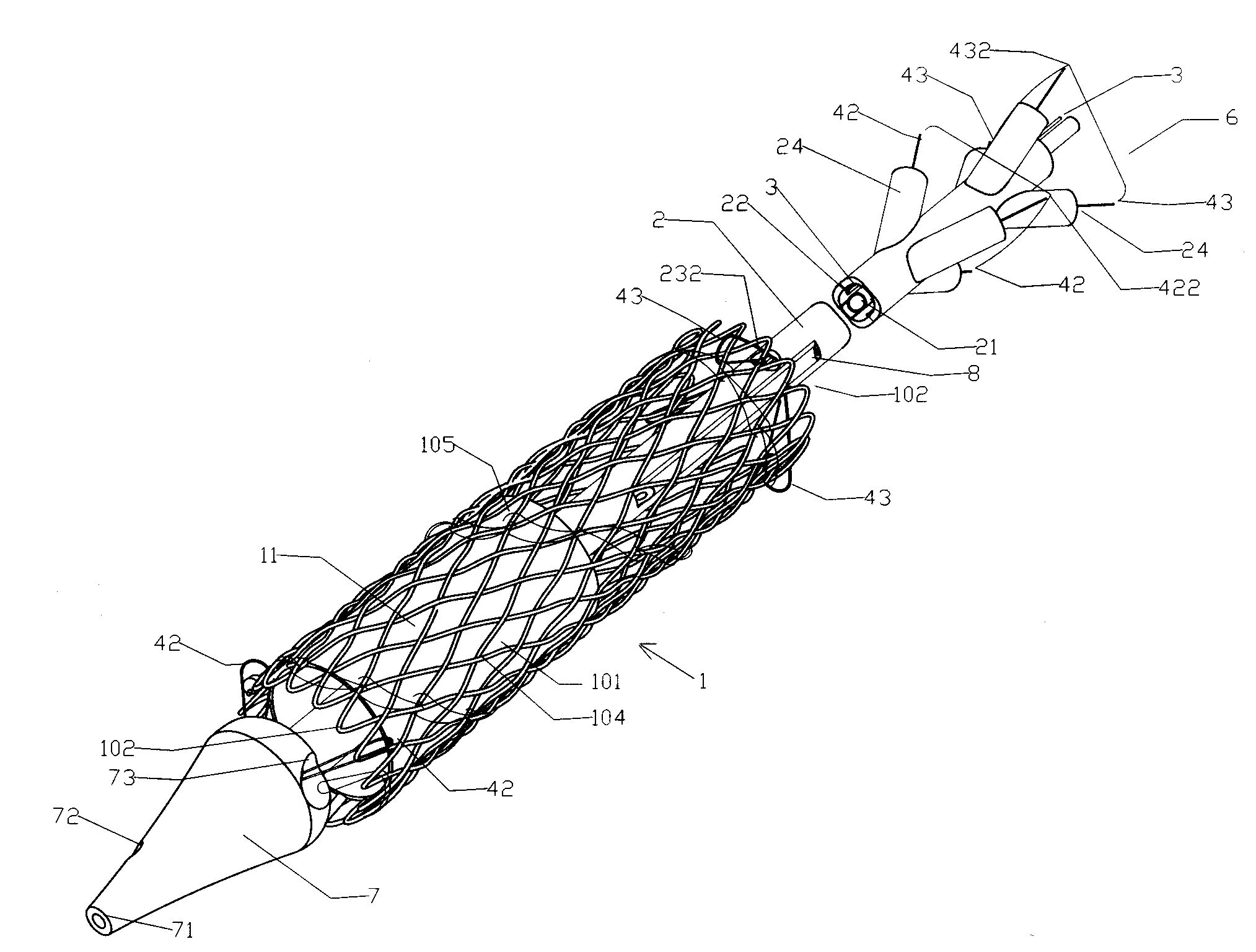
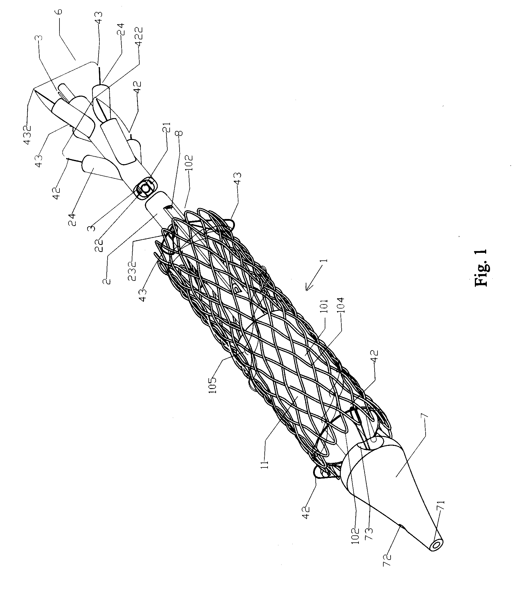
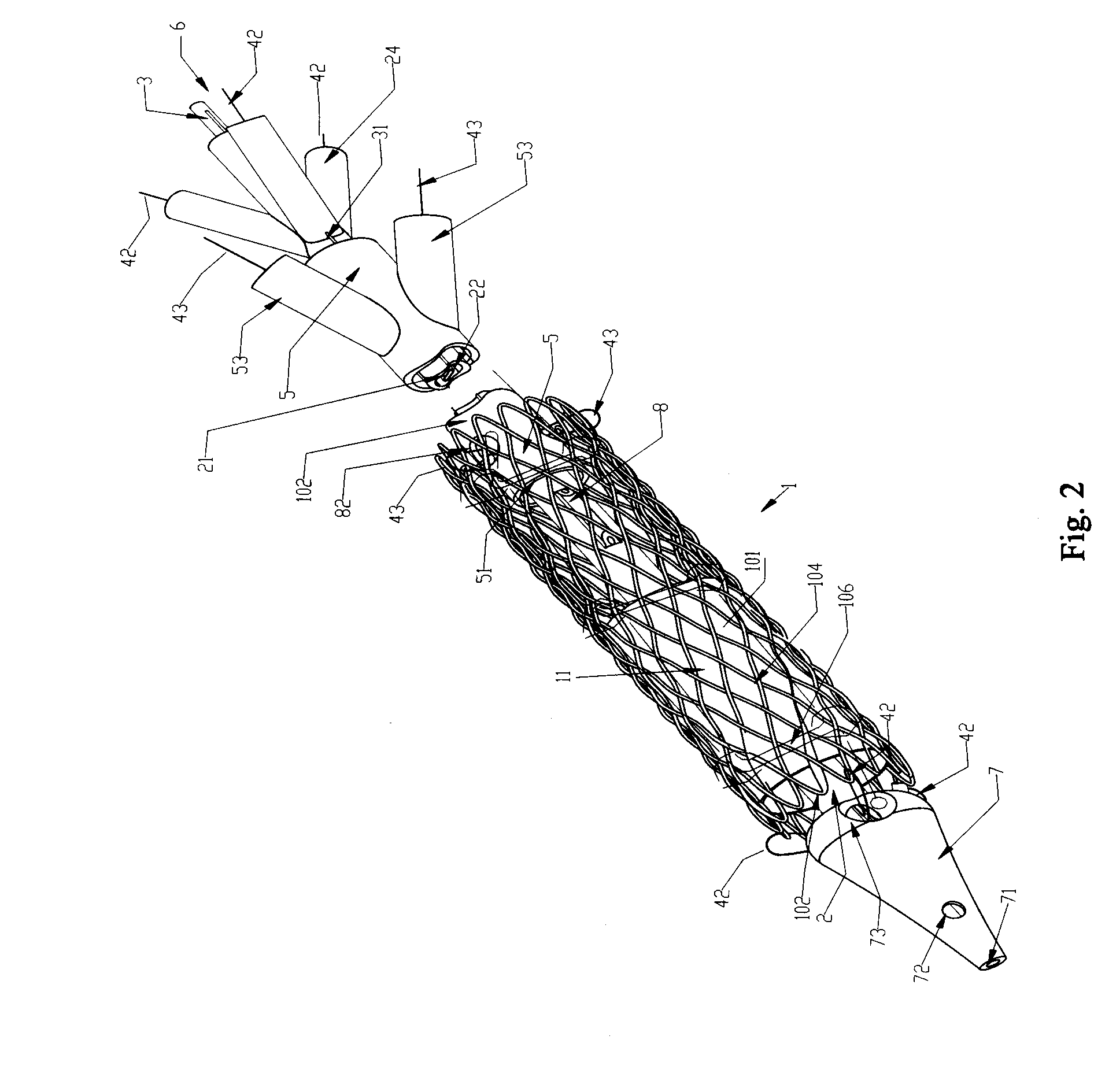
[0038]With reference to FIG. 1˜FIG. 9, the present invention, titled axial pull wire tension mechanism for self-expanding stent, is applied in the implantation of the self-expanding stent into cardiac blood vessels where it tensions the stent in collaboration with the delivery system and other stent tensioning mechanisms, of which the latter specifically refers to the flexible coupling ring tensioning mechanism and the take-up tensioning mechanism, both owned by the applicant of the present invention. (Refer to the other two patents of the applicant: “flexible coupling ring tensioning mechanism for self-expanding stent” and “take-up tensioning mechanism for self-expanding stent”)

[0039]The self-expanding stent designated as 1 in the present invention includes self-expanding stents with membranes and self-expanding stent valves, of which the former is partially or entirely covered by membranes 11 on the walls, whereas the latter, aside from being partially or entirely covered with mem...


PUM


Abstract

An axial pull wire tension mechanism for a self expanding stent includes a delivery system composed of an inner tube (2), a middle tube (5) and a lock wire (3), open wire knees (102) and / or close wire eyelets (103) at the both ends of the stent, and pull wires (4) for tensioning the stent. The pull wires (4) include at least one distal pull wire (42) and at least one proximal pull wire (43). A pull wire ring (421, 431) is provided at the distal end of each of the pull wires. Each pull wire passes through an opening of the inner tubing head (7) or the inner tube (2) or the middle tube (S) after the pull wire ring at its distal end is threaded through and locked temporarily by the lock wire, and travels between the open wire knees (102) or the close wire eyelets (103) at one end of the stent to constitute a temporary stent connection, thus forming the pull wire tension mechanism that can axially tension the stent. The present invention can locate the self-expanding stent in terms of its axial and rotational positions with great precision when in collaboration with the delivery system and the radially compression mechanism during the process of delivering the self-expanding stent into the patient's body, and is capable of either further adjustment should the position prove to be less ideal, or recycling should the stent prove to be incongruous after the expansion of the stent.

Description

TECHNICAL FIELD[0001]The present invention generally relates to a tension mechanism employed in the delivery of different stents implanted into cardiac blood vessels and other luminal human organs; particularly refers to an axial pull wire tension mechanism for self-expanding stents.BACKGROUND ART[0002]As the most important functioning human organ, the heart consists of the right chamber and the left chamber, of which each includes an atrium and a ventricle. The inter-ventricular septum separates the two ventricles whereas the inter-arterial septum divides the two atria. There is also a septum between the atrium and ventricle on each side. Four heart valves, i.e., tricuspid valve, pulmonic valve, mitral (bicuspid) valve and aortic valve, play a crucial role in the blood circulation system, wherein the anoxic blood from all body tissues enters the right atrium through superior vena cava and the inferior vena cava, and then passes through the right ventricle via tricuspid valve, where...

Claims


Application Information

Patent Timeline
IPC IPC(8): A61F2/06A61F2/90A61F2/95
CPCA61F2/90A61F2002/9511A61F2002/9505A61F2/95
Inventor WENG, NING
Owner WENG NING
Learn More