
Coherent imaging fiber based hair removal device

a hair removal device and coherent imaging technology, applied in the field of coherent imaging fiber based hair removal devices, can solve the problems of cell destruction, very patient dependent parameters, and increase the temperature of tissue, so as to increase the power level of the optical source, and add safety to the home user

Active Publication Date: 2009-04-16
THE RES FOUND OF STATE UNIV OF NEW YORK
View PDF70 Cites 15 Cited by
  • Summary
  • Abstract
  • Description
  • Claims
  • Application Information

AI Technical Summary

Benefits of technology

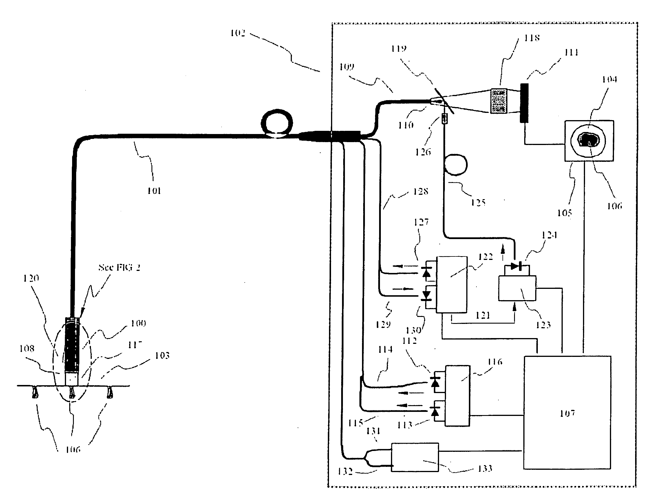
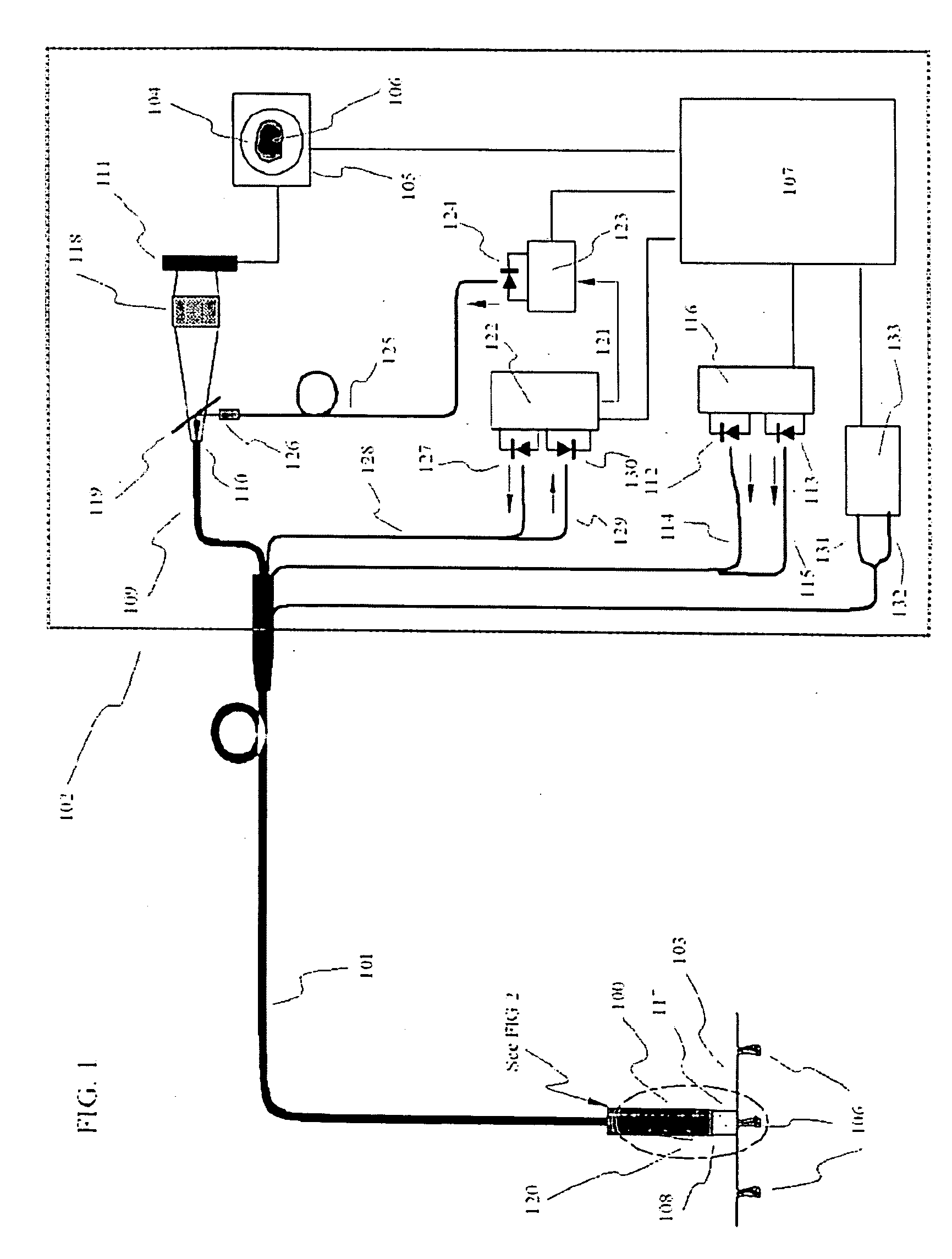
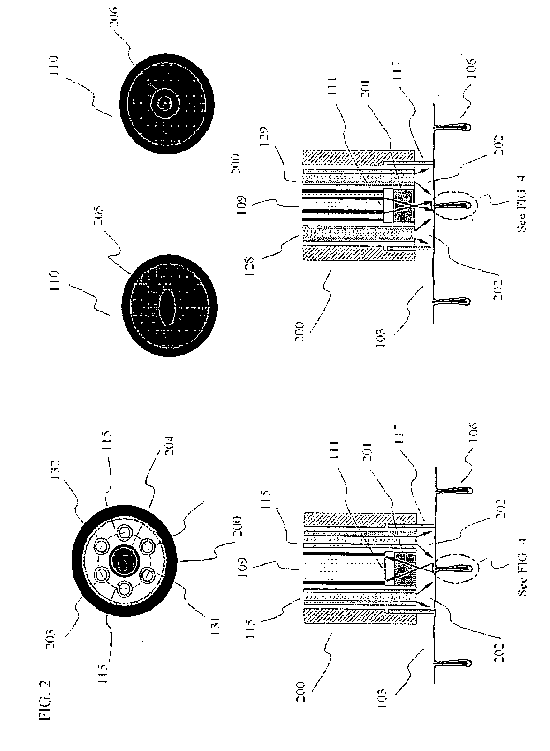
[0014]The present invention discloses a compact hand piece applicator for LHR, including a coherent imaging fiber (CIF); a fiber optic switch; optical fibers for white light illumination; chilled air delivery system; imaging optics; and an extender for the treatment spot through scanning. The coherent imaging fiber serves a dual purpose: 1) provides an image of the target area, for example, a hair follicle; 2) delivers therapeutic energy from the remote optical source to the target. The spatial cross-sectional distribution of the therapeutic laser energy can be shaped by exciting appropriate pixels in the CIF, for example, a circular spot or a donut shaped spot. The hand-piece provides the ability to alter the size of the target spot, which is expected to be smaller than the diameter of the hair follicle. The laser diode, with a wavelength in the range 750 to 850 nm, provides a broad range of pulse widths applicable to SP or ESP. The power level of the optical source can be increased through the use of multiple single LDs or a single laser diode array. The fiber optic switch, which can be replaced by an optical microphone, controls the delivery of the laser diode energy pulse or pulses. The absence of electrical signals in the hand piece offers added safety to the home user. Further the invention includes a portable electronic system which provides all the controls necessary to operate the system and to interface with other computing devices.

Problems solved by technology

However, unavoidable absorption of photons in the epidermis leads to heat, which needs to be removed if damage to the epidermis is to be avoided.
Some photons are absorbed in the epidermis, while the remaining migrate, via scattering through the dermis and reach the melanin rich hair shaft and bulb region, where absorption leads to elevation of tissue temperature causing cell destruction.
Unfortunately, these parameters are also very patient dependent and use of LHR devices remains somewhat of an art.
Consequently, this leads to bulky and expensive machines, which need full medical facilities for operation.
While the large diameter reduces treatment time and increases penetration depth into the dermis, it lacks the capability to selectively remove hair from a given area, i.e. reduce hair density.
Pre-treatments can be used vital any of the light-based techniques to enhance the efficacy of hair removal, but adds extra time and cost to the treatment.
However, the minimum spot size of 0.25 cm2 is too large for targeting single hair follicles and thereby causing a reduction in the peak power requirement and their system lacks any imaging device for identifying treatment area.
However, the said photo cosmetic device does not include an imaging capability and uses lower power EMR sources with prolonged exposure times. For hair removal they recommend power levels in the range of 20-500 W, not attainable by a single laser diodes.

Method used


Image

  • Coherent imaging fiber based hair removal device
  • Coherent imaging fiber based hair removal device
  • Coherent imaging fiber based hair removal device

Examples


Embodiment Construction

[0025]The following detailed description of preferred embodiments of the invention will be made in reference to the accompanying drawings. In describing the invention, explanation about related functions or constructions known in the art are omitted for the sake of clearness in understanding the concept of the invention, to avoid obscuring the invention with unnecessary detail.

[0026]The present invention discloses a portable an inexpensive apparatus for locating and capturing the image of a small treatment area, typically, about 250 microns in diameter. Further more the said imaging hand piece, typically less thin 15 mm in diameter, provides for a means to deliver optical energy from a remote source to the target area, preferably smaller than the image size. The small size the hand piece is particularly useful for treatment areas that require a reduction of the hair density and not indiscriminate hair removal. In a preferred embodiment, the hand piece is mounted on a robotic arm for...


PUM


Abstract

A photoepilation device including a compact hand piece applicator and a portable electronics module for use in a non-medical setting. The hand piece, which contains no electrical signals, allows the user to focus on individual hair follicles by observing a magnified image provided on a semiconductor display. The image from the hand piece is transported to a remote CCD through a coherent imaging fiber, which also delivers the therapeutic energy pulse from a remotely located source to the localized target. Destruction of pluripotential follicular stems cells found in the hair bulb and bulge regions is possible via a single low power laser diode. Control of pulse width and spot size attains a range of fluence levels up to 85 J·cm−2.

Description

PRIORITY[0001]This application claims priority to U.S. Provisional Application No. 60 / 977,851, filed Oct. 5, 2007, the contents of which is incorporated herein by reference.BACKGROUND OF THE INVENTION[0002]1. Field of the Invention[0003]The present invention relates to methods and apparatus utilizing selective and extended photothermolysis for various cosmetic, health and dermatology conditions, particularly, to techniques using lower power laser diodes for the inexpensive manufacture of safe products that can be used in non-medical facilities such as spas, salons and the home.[0004]2. Brief Description of the Background Art[0005]Electromagnetic energy, particularly in the optical band 400 nm to 1200 nm, has been used for treatment of many skin related diseases as well as for cosmetic procedures, such as, hair removal, spider veins, tattoos, port wine stains, and for skin rejuvenation and photodynamic therapy. Laser- and light-based removal of hair, both in men and women, is widely ...

Claims


Application Information

Patent Timeline
IPC IPC(8): A61B18/22
CPCA61B18/203A61B2018/00476A61B2018/00452
Inventor DHADWAL, HARBANS S.
Owner THE RES FOUND OF STATE UNIV OF NEW YORK
Learn More