
System for forming holes in metal sheet

Inactive Publication Date: 2009-04-16
HONDA MOTOR CO LTD
View PDF11 Cites 11 Cited by
  • Summary
  • Abstract
  • Description
  • Claims
  • Application Information

AI Technical Summary

Benefits of technology

[0013]The rigidity increases with increased minimum distance between the edge of a hole and the edge of an adjacent hole. If the pitch is the same, the minimum distance between the edge of an oblong hole extending in the longitudinal direction and the edge of an adjacent oblong hole is greater than the minimum distance between the edge of a round hole and the edge of an adjacent round hole, and ductility can therefore be increased according to the present invention.
[0017]Oblong holes are selected when the tensile direction is specified, and round holes are selected when the tensile direction is not specified. The hole selection can be easily made. As a result of testing, it is possible to increase tensile strength by arranging the oblong holes or round holes at the points of intersection of a lattice.
[0019]The plastic working conditions of a mild steel blank material and a high-tensile steel sheet in which no holes have been made can be easily established. The plastic working conditions of the perforated sheet are established based on these easily established plastic working conditions. The result is that the conditions to work the perforated sheet can be easily established, and plastic working can be performed quickly.
[0021]The calculation time increases when an attempt is made to determine the mechanical characteristics of the perforated sheet through calculation. The mechanical characteristics of a member that does not have any holes, on the other hand, can be easily found through calculation.
[0022]In a perforated sheet composed of hole formation areas and a remaining area in which holes are not formed, the hole formation areas are replaced by solid areas having low rigidity, for example. The mechanical characteristics are calculated after the manner of a perforated sheet composed of solid areas of low rigidity and a remaining area. In other words, according to the present invention, the mechanical characteristics of a perforated sheet can be determined in a short amount of calculation time.

Problems solved by technology

Therefore, stretching is restricted in the perforated sheet.
When an attempt is made to use calculations to determine the mechanical characteristics of a perforated sheet obtained by forming holes in a metal sheet, the calculations become complicated.

Method used


Image

  • System for forming holes in metal sheet
  • System for forming holes in metal sheet
  • System for forming holes in metal sheet

Examples


Embodiment Construction

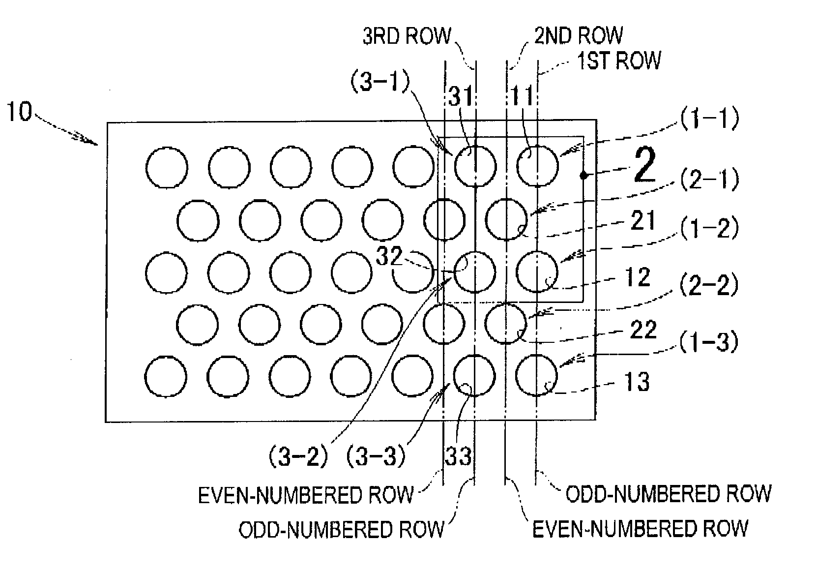
[0069]A first model 10 shown in FIG. 1 is a perforated sheet in which holes 11, 12, 13, 21, 22, 31, 32, 33 are formed in regular order by punching or another method in a metal sheet. The first model 10 is stretched parallel to the transverse sides.

[0070]A line passing through the centers of the holes 11, 12, 13 is drawn parallel to the longitudinal sides of the model 10, and the group of holes disposed along this line is referred to as a row.

[0071]Furthermore, progressing from the right side of the drawing, the rows are referred to as the first row, the second row, and the third row; the holes progressing down from the first hole at the top of the first row are denoted in sequence as (1-1) hole 11, (1-2) hole 12, and (1-3) hole 13; the holes progressing downward from the first hole at the top of the second row are denoted in sequence as (2-1) hole 21 and (2-2) hole 22; and the holes progressing downward from the first hole at the top of the third row are denoted in sequence as (3-1)...


PUM

PropertyMeasurementUnit
Fractionaaaaaaaaaa
Lengthaaaaaaaaaa
Shapeaaaaaaaaaa

Abstract

A perforated sheet obtained by forming holes in regular order in a metal sheet, the perforated sheet having holes arranged so that in a case of drawing a first tangential line extending in the tensile direction and passing through the bottom edge of a (1-1) hole, a second tangential line passing through the top edge of a (2-1) hole, a third tangential line passing through the bottom edge of the (2-1) hole, and a fourth tangential line passing through the top edge of a (1-2) hole, the second tangential line passes between the first tangential line and the fourth tangential line, and the third tangential line passes between the first tangential line and the fourth tangential line.

Description

FIELD OF THE INVENTION[0001]The present invention relates to a system for forming round or oblong holes in a metal sheet.BACKGROUND OF THE INVENTION[0002]With the demand for weight reduction in vehicle bodies, it has become possible to use a perforated sheet in part of a vehicle body, as shown in Japanese Patent Application Laid-Open Publication No. 2004-82796 (JP 2004-082796 A), for example. The perforated sheet is described with reference to FIG. 41 hereof.[0003]As shown in FIG. 41, a vehicle hood 100 is composed of a hood outer panel 101, and a hood inner panel 102 superposed over the hood outer panel 101. The hood inner panel 102 is a perforated sheet wherein holes 103 are formed in regular order in a metal sheet.[0004]Since the hood inner panel 102 is made more lightweight in proportion to the large number of holes 103, weight reduction in the hood 100 can be achieved.[0005]When the hood 100 is subjected to tension, the hood 100 stretches. The stretching improves the capacity t...

Claims


Application Information

Patent Timeline
IPC IPC(8): B32B3/10B23P15/00B32B15/00G01N3/00
CPCB21D28/26B21D47/04Y10T428/12361E04C2/08Y10T29/496B21D53/88
Inventor MATSUYAMA, SHOHEI
Owner HONDA MOTOR CO LTD
Learn More