Enclosure for electric equipment and imaging device
a technology for enclosures and electronic equipment, applied in the field of enclosures for electronic equipment and imaging devices, can solve the problems of poor assembling performance, lack of designability, poor assembling performance, etc., and achieve the effect of preventing the inverse insertion of batteries, excellent assembling performance and heat transfer properties, and reducing the number of parts
- Summary
- Abstract
- Description
- Claims
- Application Information
AI Technical Summary
Benefits of technology
Problems solved by technology
Method used
Image
Examples
first embodiment
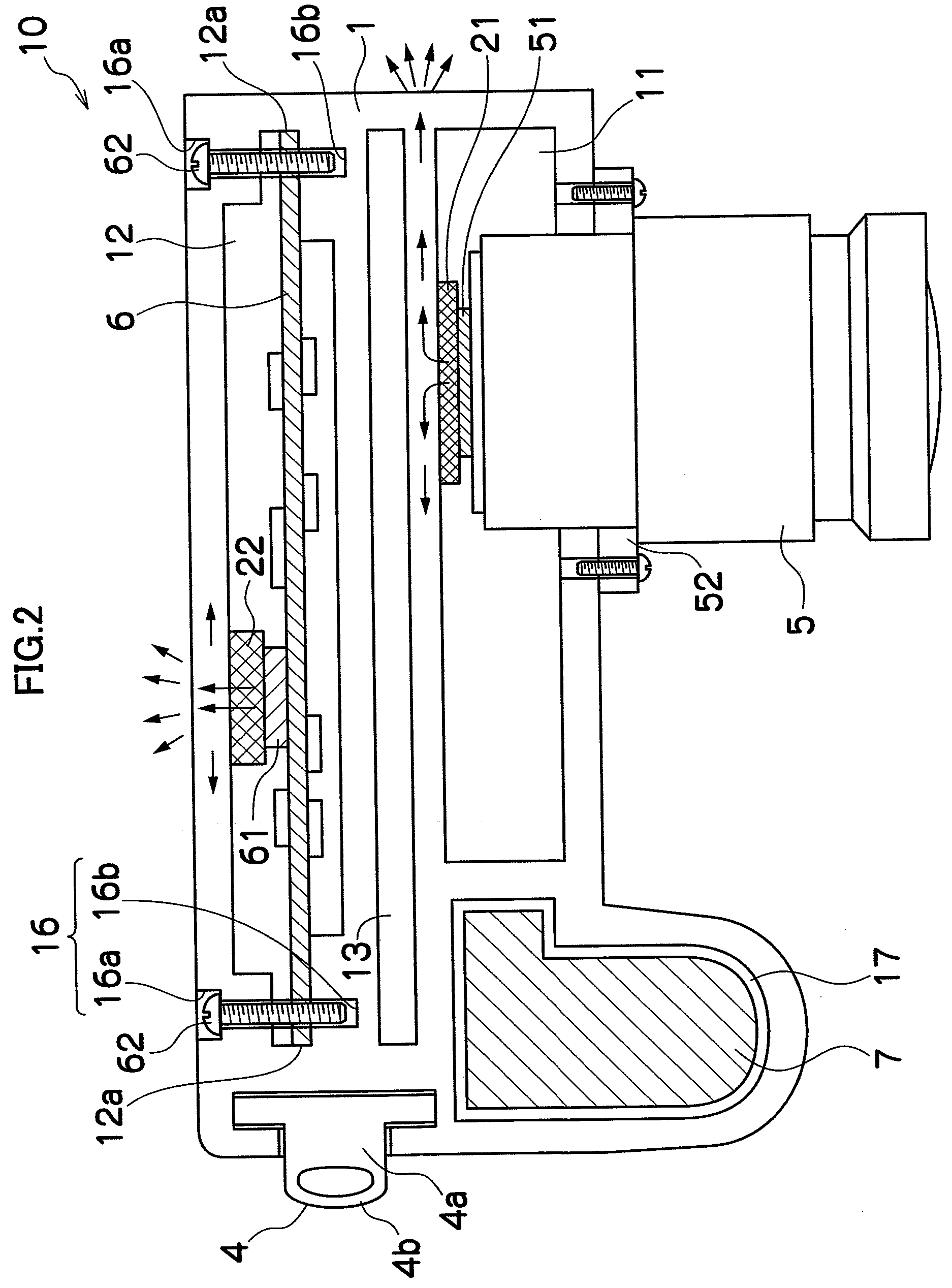
[0040]FIG. 1A is a perspective view of a digital camera 10 using a digital camera enclosure 1 according to a first embodiment of the present invention, and FIG. 1B is a perspective view of the digital camera enclosure 1. FIG. 2 is a perspective view of an essential part of the digital camera 10 using the digital camera enclosure 1.
[0041]The digital camera 10 mainly comprises the digital camera enclosure 1, an upper plate 2, a lower plate 3, a strap mounting member 4, and a lens barrel 5.
[0042]The digital camera enclosure 1 is formed of aluminum alloy and molded by extrusion molding by extrusion in the vertical direction of the enclosure (vertical extrusion). As the aluminum alloy used in the digital camera enclosure 1, Al—Mg—Si A6063, Al—Mn A3003, A3004 and the like excellent in extrusion performance, corrosion resistance and surface treatment performance can be used, considering strength, moldability, cost and the like. Various metal materials including magnesium alloy, stainless a...
second embodiment
[0072]A second embodiment is different from the first embodiment in mounting of the lens barrel, in which a decoration ring is used.
[0073]FIG. 5 is a partial sectional view of a digital camera enclosure 1′ of the second embodiment. The same reference numerals are given to the same portions as those in the first embodiment, and the description will be omitted.
[Structure of the Digital Camera Enclosure 1′]
[0074]A lens barrel mounting portion 15′ is formed by post machining on the wall on the front face side of the optical system accommodation portion 11 and constituted by a hole 15a′ having a diameter larger than the maximum diameter of the lens barrel 5′ and four screw holes 15b′ formed by post machining on the wall on the rear face side of the optical system accommodation portion 11 and used when the lens barrel 5 is fixed to the digital camera enclosure 1′. It is only necessary that the number of the screw holes 15b′ may be three or more and not limited to four.
[Mounting of Compone...
third embodiment
[0078]A third embodiment is different from the first and second embodiments in mounting of the lens barrel, in which mounting accuracy and mounting strength of the lens barrel are improved as compared with those in the first embodiment.
[0079]FIG. 6A is a partial sectional view of a digital camera enclosure 1″ of the third embodiment, FIG. 6B is a front view of a lens barrel mounting portion 15″, and FIG. 6C is a front view of a lens barrel 5″. The same reference numerals are given to the same portions as those in the first embodiment, and the description will be omitted.
[Structure of the Digital Camera Enclosure 1″]
[0080]The lens barrel mounting portion 15″ is formed by post machining and constituted by a hole 15a″ into which a body portion of the lens barrel 5″ can be fitted and screw holes 15b″ and 15c″ used when the lens barrel 5″ is fixed on the digital camera enclosure 1″.
[0081]The hole 15a″ is formed on the wall on the front face side of the optical system accommodation portio...
PUM
 Abstract
Description
Claims
Application Information
 - R&D
- Intellectual Property
- Life Sciences
- Materials
- Tech Scout
- Unparalleled Data Quality
- Higher Quality Content
- 60% Fewer Hallucinations
Browse by: Latest US Patents, China's latest patents, Technical Efficacy Thesaurus, Application Domain, Technology Topic, Popular Technical Reports.
© 2025 PatSnap. All rights reserved.Legal|Privacy policy|Modern Slavery Act Transparency Statement|Sitemap|About US| Contact US: help@patsnap.com


