Wearable chemcial dispenser

a dispenser and wearable technology, applied in the direction of disinfection, transportation and packaging, liquid transfer devices, etc., can solve the problems of increasing the overall cost of protection, not making a repeat application, and not understanding how long a particular application of the chemical is likely to remain effective, etc., to achieve the effect of convenient for consumers to understand and use, and less production costs

Active Publication Date: 2009-01-08
SC JOHNSON & SON INC
View PDF17 Cites 44 Cited by
  • Summary
  • Abstract
  • Description
  • Claims
  • Application Information

AI Technical Summary

Benefits of technology

[0017]In other preferred forms the substrate comprises a use-up cue that changes appearance by evaporation of a material in a direction toward the table when the substrate is in place on the table, wherein the finger has a side extension that, as the finger is rotated by interaction with the projection of the shutter as the shutter is moved, moves from a position inhibiting the evaporation of material from the use-up cue to a second position wherein evaporation of material from the use-up cue is readily permitted. The shutter, when in its closed position, can close both the inlet and outlet.
[0021]Other preferred aspects include that the substrate has an air permeable section bearing the air treatment chemical and a shell portion containing a volatile use-up cue chemical. There is a finger mounted for rotation on its own longitudinal axis. A portion of the finger can permit diffusion of the use-up cue chemical from the shell when the finger is in a first rotational position, and can restrict diffusion of the use-up cue chemical from the shell when in a second rotational position. Movement of a cam projection can drive the finger from the second rotational position to the first rotational position.
[0024]In preferred forms the slab structure also has a shell cavity retaining a use-up cue chemical, the cavity having an essentially transparent wall along one of the opposed facing surfaces, the shell cavity is covered by a peel-off cover along the other of the opposed facing surfaces, there is a through slot positioned between the air permeable section and the shell, and there is an indentation along a peripheral portion of the substrate so as to help avoid insertion of the substrate in the dispenser in an inside out manner.
[0025]When the on / off switch is moved to the on position, the finger moves away from covering an exit of the shell (permitting the use-up cue chemical to continue to diffuse). When operation of the device is suspended by movement of the on / off switch, the finger again covers the exit of the shell, preserving the use-up cue chemical when the fan is off, and better coordinating the use-up cue life to that of the impregnated substrate portion.
[0029]The devices and refills of the present invention have a variety of important advantages. A consumer merely needs to operate a single on / off switch to control blower operation, shut off the entry and exit of air from the external environment between uses, and close off use-up cue chemical diffusion between uses. Structures associated therewith prevent motor operation when the impregnated refill has not yet been installed, and also prevent improper installation of the substrate.
[0030]These devices and refills are relatively inexpensive to produce, and are suitable for consumers to understand and use without extensive instructions. Further, these devices can be made lightweight, and thus can be worn hanging from a clothing item.

Problems solved by technology

However, if a consumer does not read the label or other instructions associated therewith they may not understand how long a particular application of the chemical is likely to remain most effective.
This may lead the consumer to prematurely apply additional product before it is necessary to do so, thereby increasing the overall cost of protection.
Alternatively, they may not make a repeat application of product soon enough, until after the effectiveness of the product has decreased dramatically.
This may lead to consumer dissatisfaction.
For example, where the product is intended to be sprayed on clothing, this will limit how the spray is formulated (e.g. to avoid using certain otherwise preferred solvents or actives that can stain certain fabrics).
This can increase costs, or require some compromises with respect to other desired attributes (e.g. perceived feel).
Moreover, even where the formulations are designed to be sprayed directly on even very delicate clothing, consumers may be unwilling to test that out, and thus avoid the product regardless of its suitability.
Similarly, notwithstanding suitability, some consumers have expressed a reluctance to apply insect repellents directly to their skin.
However, some such devices blow the active too far out away from the human body, causing too little of the active to reach locations of primary concern (e.g. near ankles).
Other such devices don't provide a way of minimizing waste of the active, such as while blower operation is suspended between uses.
Still other such devices are unduly costly, are too heavy, or have other deficiencies (such as not providing sufficient feedback to the consumer when the device is otherwise operating ineffectively).

Method used


Image

  • Wearable chemcial dispenser
  • Wearable chemcial dispenser
  • Wearable chemcial dispenser

Examples


Embodiment Construction

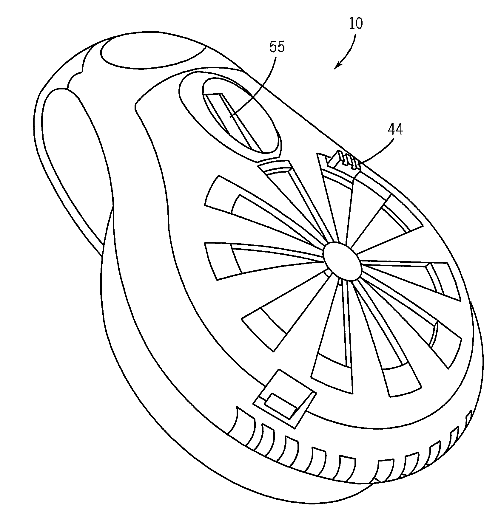
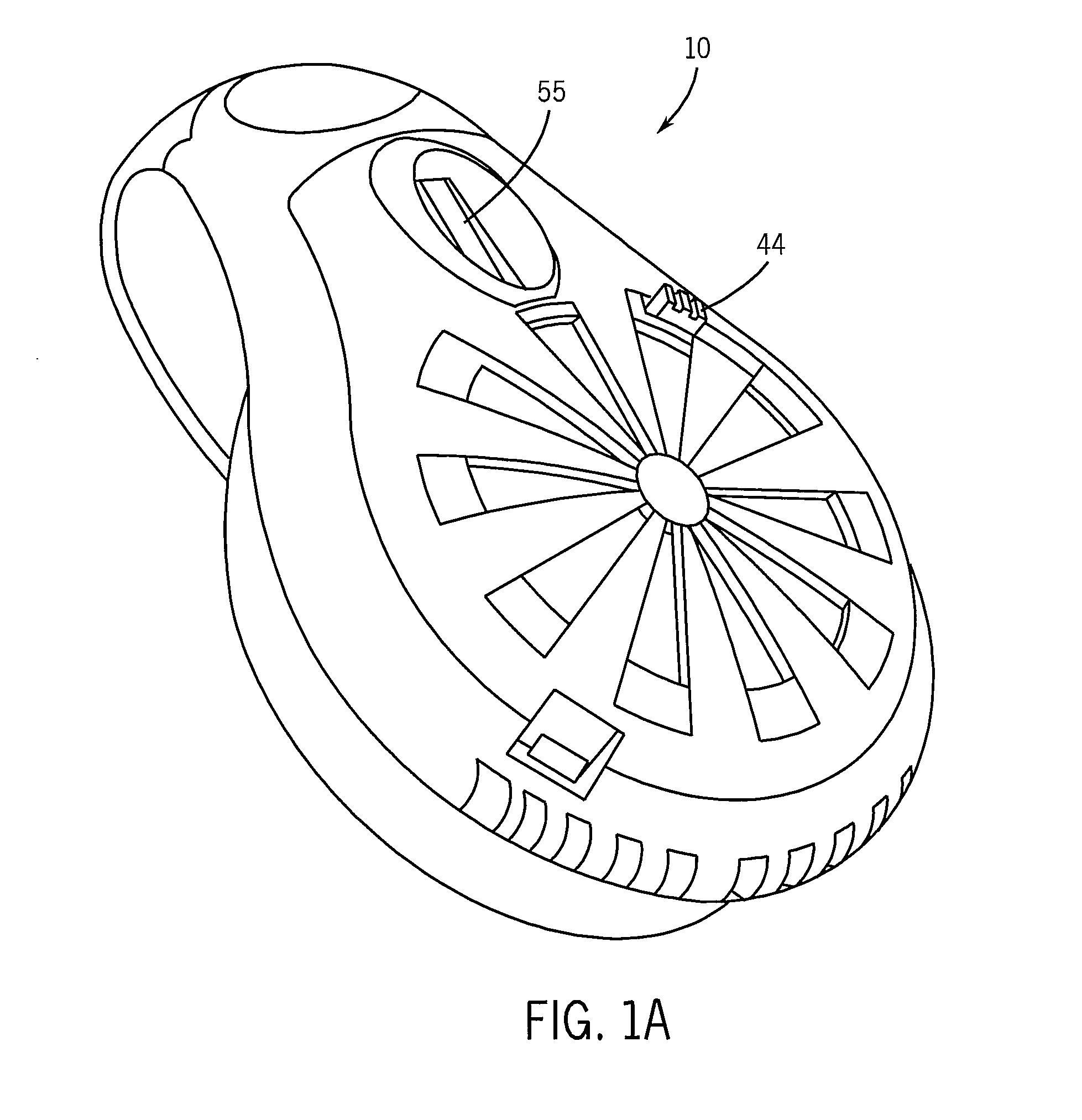
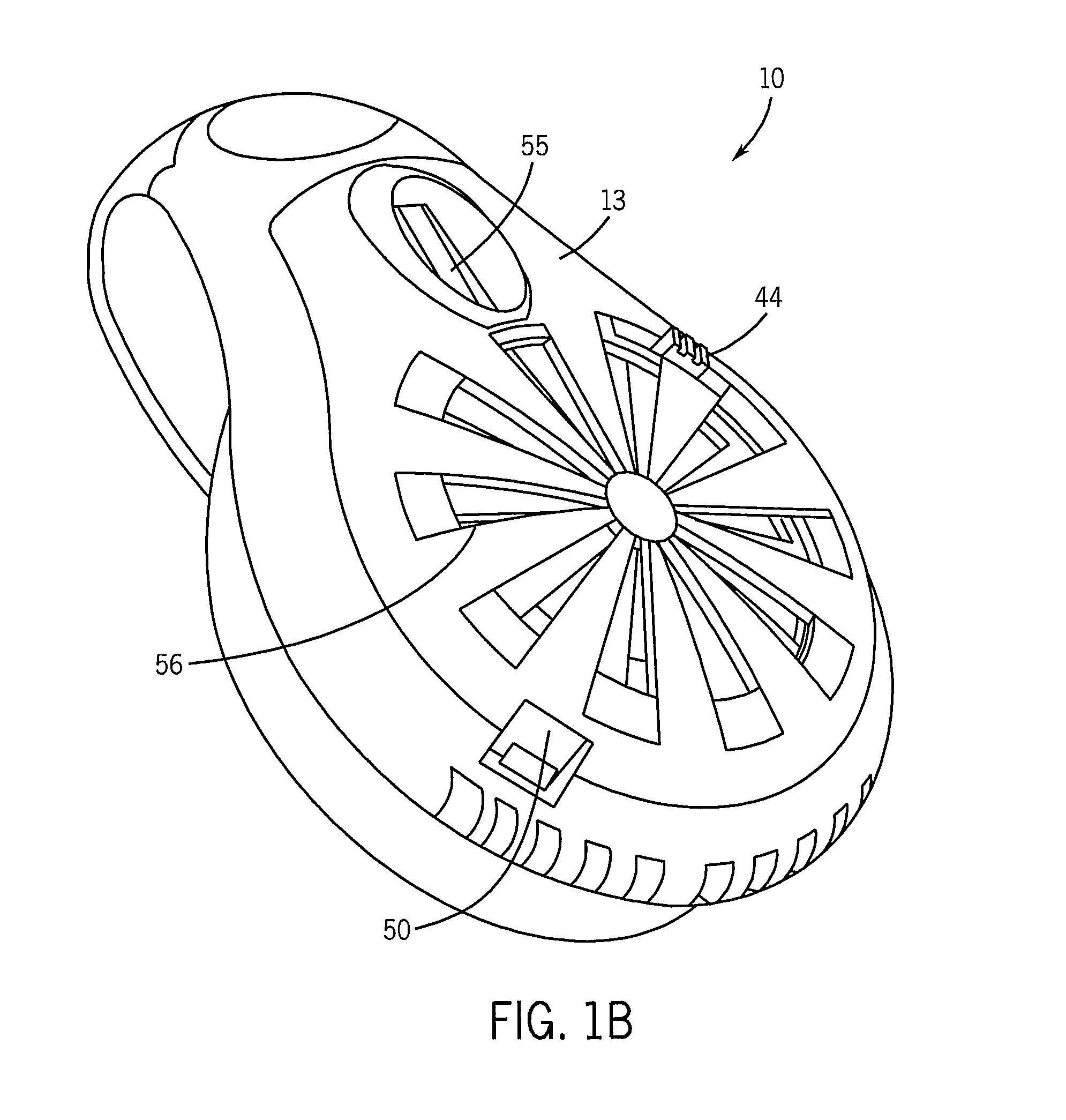
[0043]Referring first to FIGS. 1A, 1B and 2, there is shown a dispensing device 10. It has a main housing section 11, an intermediate housing section 12, an outer cover section 13 and a base cover section 14. The region between the main housing section 11 and the base cover section 14 houses the primary electrical parts.

[0044]In this regard, there are two AA batteries 16 which are in electrical contact with linkages 17, that in turn are connected to a spring-type switch 18, which (when the switch is closed) powers a small motor 19. An example of this type of switch is a micro-leaf switch of the sort available from the Wealth Metal Factory Ltd. of Hong Kong, China.

[0045]The motor 19 has a stem 20. That stem can be linked to the center of rotor 21 having vanes 24. When the motor receives power, stem 20 rotates and carries with it the rotor 21. The vanes on the rotor are aligned such that the rotation sucks air in through the openings 56 of the outer cover section 13 and then forces th...


PUM


Abstract

Disclosed herein are wearable devices for dispensing insect repellents, fragrances, and / or other chemicals along the outside of the clothing of a human, to avoid the need to apply such chemicals directly to clothing or to human's skin. The devices have an on / off switch that automatically controls a shutter which enables and restricts air flow, while also controlling fan operation and covering of a use-up cue. The device also is designed to prevent fan operation when an impregnated slab is not present. Also disclosed are preferred refills for use with such devices.

Description

CROSS-REFERENCE TO RELATED APPLICATIONS[0001]Not applicable.STATEMENT REGARDING FEDERALLY SPONSORED RESEARCH / DEVELOPMENT[0002]Not applicableBACKGROUND OF THE INVENTION[0003]The present invention relates to wearable devices that dispense chemicals such as insect repellents and / or fragrances.[0004]Various techniques have been developed to provide humans with protection from insect bites. For insect control inside buildings a primary emphasis is placed on trying to keep insects from entering the building at all (e.g. placing screens over windows). This sometimes is supplemented with chemical treatment of room air and / or the use of traps. See e.g. U.S. Pat. Nos. 6,582,714 and 7,175,815, and also U.S. patent application publications 2005 / 0079113, 2006 / 0039835, 2006 / 0137241 and 2007 / 0036688.[0005]When the individual is outdoors where the area can't be effectively screened, and the individual is mostly staying in a particular area (e.g. at a picnic, or on a patio near a building), traps an...

Claims


Application Information

Patent Timeline
IPC IPC(8): B05B15/06
CPCA01M1/2033A61L9/122A01M1/2055
Inventor SCHUMACHER, DONALD J.ALFARO, RAYMUND J.NICKEL, DIRK K.DUSTON, TYLER D.HUDAK, MICHAEL T.KINGSTON, SEAN P.MAGHASI, ANNE T.DEGRAFT-JOHNSON, KWAMENA GYAKYE
Owner SC JOHNSON & SON INC
Why Eureka
Try Eureka