Thermistor
a technology of thermoplastic and insulating layer, applied in the direction of resistor details, current responsive resistors, varistors, etc., can solve the problems of difficult to improve the oxygen blocking characteristic, difficult to apply a resin layer thicker than a conventional one, and difficult to isolate the sealed section, so as to reduce the characteristic, prevent the permeation of oxygen and other components, and improve the effect of oxygen blocking characteristi
- Summary
- Abstract
- Description
- Claims
- Application Information
AI Technical Summary
Benefits of technology
Problems solved by technology
Method used
Image


Examples
first embodiment
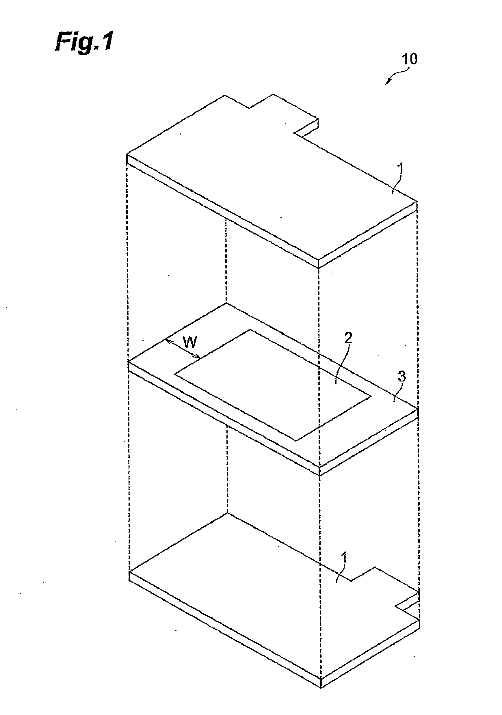
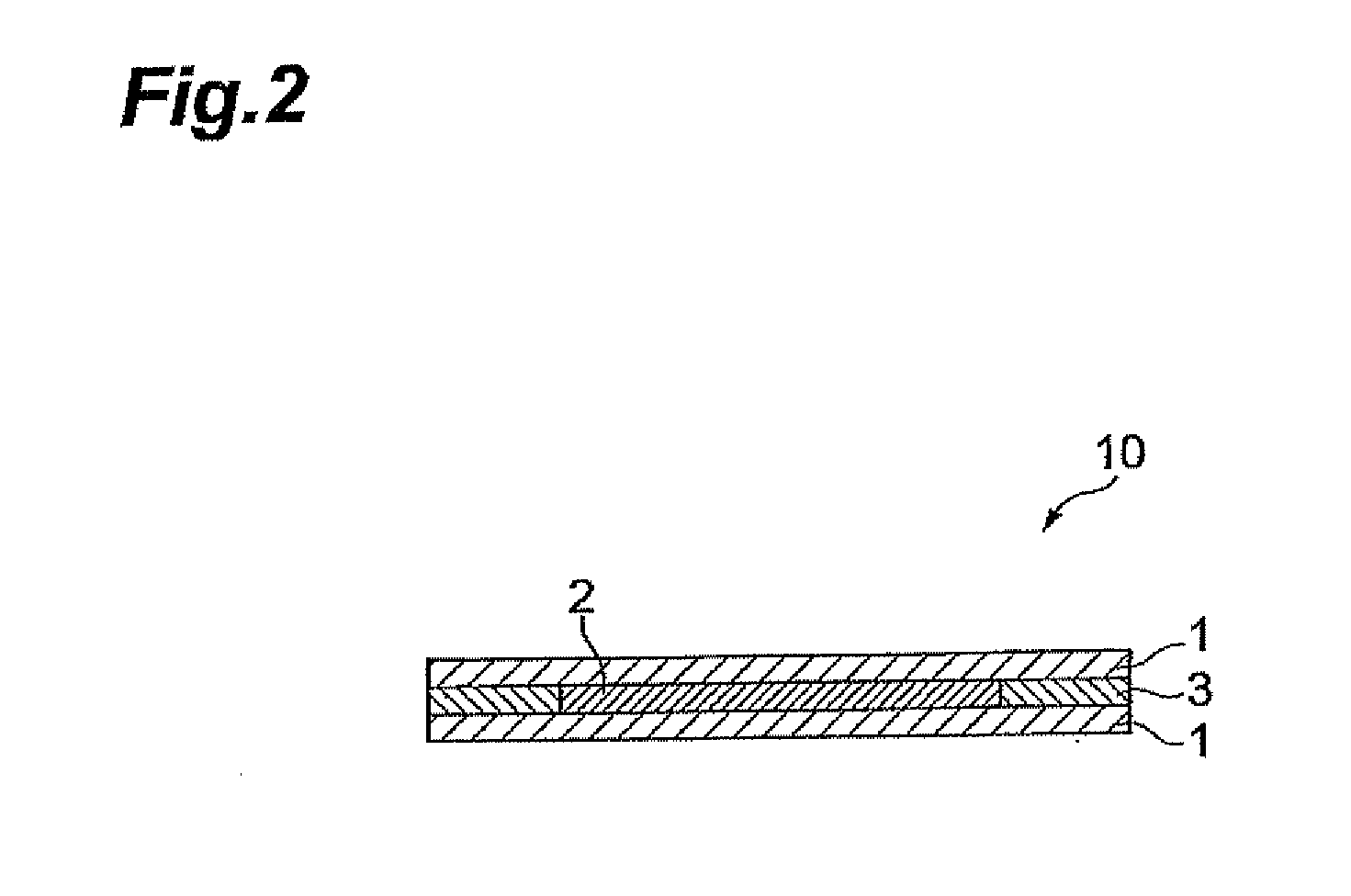
[0022]FIG. 1 is an exploded perspective view of the configuration of a thermistor according to a first embodiment. FIG. 2 is a longitudinal cross-sectional view of the configuration of the thermistor according to the first embodiment.
[0023]As shown in the drawings, a thermistor 10 according to this embodiment includes a thermistor layer 2 interposed between paired electrodes 1 and is a flat rectangular solid. A sealing resin 3 surrounds the thermistor layer 2 between the paired electrodes 1. If necessary, the thermistor 10 may further include leads (not shown) electrically connected to the electrodes 1. Such a thermistor 10 can be suitably used, for example, as an overcurrent / overheat protecting element, a self-regulating heating element, or a temperature sensor.
[0024]Each of the paired electrodes 1 is shaped into a plate or foil. According to this embodiment, a protrusion that functions as a connection terminal for an external unit is provided on one side of the electrode 1. The tw...
second embodiment
[0050]FIG. 3 is an exploded perspective view of the configuration of a thermistor according to a second embodiment. FIG. 4 is a longitudinal cross-sectional view of the configuration of the thermistor according to the second embodiment.
[0051]As shown in the drawings, a thermistor 20 according to this embodiment includes a thermistor layer 12 and paired first electrodes 14 sandwiching the thermistor layer 12, and paired second electrodes 11 disposed outside the respective first electrodes 14 so as to sandwich the thermistor layer 12. The entire thermistor 20 is a flat rectangular solid. A sealing resin 13 is disposed in an area outside the thermistor layer 2 interposed between the paired second electrodes 11.
[0052]In the thermistor 20, the first electrodes 14 and the second electrodes 11 may be composed of the same material as that of the electrodes 1 in the first embodiment, and the thermistor layer 12 may be composed of the same material as that of the thermistor layer 2 in the fir...
example 1
[0065]First, filamentary Ni particles were added to high-density polyethylene (melting point: 130° C., density: 0.92 g / cm3) in an amount equal to 35 volume % of the high-density polyethylene; and the mixture was kneaded for 30 minutes in a Labo Plastmill while being heated at 150° C. to prepare a kneaded material in which Ni particles were dispersed. The resulting kneaded material was formed into a 0.8-mm thick sheet for a thermistor by heat-pressing at 150° C.
[0066]Next, the resulting sheet was interposed between two Ni foils, each having one roughened surface; the Ni foils were fixed by heating and pressurizing the entire composite by heat-pressing; and a 0.4-mm thick sheet with Ni foils was produced. This sheet was cut into pieces of 9.0×3.6 mm; then, the pieces were irradiated with radiation to crosslink the high-density polyethylene; and a thermistor element having a configuration in which a thermistor layer is interposed between Ni foils was produced.
[0067]Then, the crosslinke...
PUM
 Abstract
Description
Claims
Application Information
 - R&D
- Intellectual Property
- Life Sciences
- Materials
- Tech Scout
- Unparalleled Data Quality
- Higher Quality Content
- 60% Fewer Hallucinations
Browse by: Latest US Patents, China's latest patents, Technical Efficacy Thesaurus, Application Domain, Technology Topic, Popular Technical Reports.
© 2025 PatSnap. All rights reserved.Legal|Privacy policy|Modern Slavery Act Transparency Statement|Sitemap|About US| Contact US: help@patsnap.com