
Floor tile with adhesively bonded concrete

Inactive Publication Date: 2009-04-02
GLOBAL INTEGRATED FLOORING SOLUTIONS INC
View PDF42 Cites 10 Cited by
  • Summary
  • Abstract
  • Description
  • Claims
  • Application Information

AI Technical Summary

Benefits of technology

[0020]As an alternative construction and forming process for the floor tile, the metal floor pan can have the shallow upwardly-opening compartment thereof filled with wet concrete. Prior to pouring of the wet concrete into the pan, however, the interior surfaces of the bottom and side walls of the pan are coated with a suitable adhesive, such as a hot melt. The adhesive coating as applied to at least the bottom wall of the pan is also then provided with a layer of fine-grained sand sprinkled thereover, which sand is effectively wetted and embedded into the adhesive layer. A wet concrete mix, which also has an adhesive mixed therein, is then poured into the pan so as to fill the compartment. The adhesive in the concrete readily cooperates with the sand layer and adhesive pre-applied to the pan to create a highly effective and strong securement of the concrete to the pan as the concrete hardens and cures within the pan. As an alternative to the above, rather than including adhesive within the wet concrete mix, a second layer of adhesive can be sprayed into the pan after the sand layer has been applied, following which the wet concrete can be poured into the pan and allowed to cure and harden while the adhesive arrangement creates a secure and strong fixed securement of the hardened concrete core to the metal pan.
[0021]The raised floor system of the invention incorporates a grid of height-adjustable pedestals which individually provide a top support plate to function as a support for engagement with corner portions of four adjacent floor tiles. This top support plate has upwardly-protruding positioning elements which are adapted to project into small gaps defined between sidewardly adjacent floor tiles for ensuring proper positioning of the tiles with respect to one another and with respect to the pedestal. A fastener such as an elongate screw projects vertically downwardly adjacent the corner of the floor tiles for threaded engagement with the pedestal arrangement. The fastener cooperates with a hold-down member, such as an annular washer which in turn cooperates with corners of the floor tiles to effect fixing of the floor tiles relative to the pedestal head when the fastener is tightened.

Problems solved by technology

In known floor systems employing composite steel and concrete floor tiles, which tiles in plan view are typically relatively large squares having side dimensions of about 24 inches, the tiles due to their construction and size are necessarily both bulky and heavy so that transport of such tiles over long distances is undesirably costly.
Further, filling the metal pans with wet concrete and achieving a proper structural interconnection of the hardened concrete to the metal pan so as to provide the finished floor tile, when in use, with the necessary strength and durability, has presented an ongoing problem.
While these techniques have proven to improve the strength characteristics, these techniques also increase the complexities associated both with the manufacture of the pan and the forming of the concrete therein.
This, however, creates additional disadvantages due not only to the expense of gypsum cement, but also due to its characteristics.
Specifically, concrete mix formed using gypsum cement experiences dimensional instability in that the concrete dimensionally changes, specifically grows, during drying or curing.
This hence creates significant dimensional instability with respect to the finished floor tile, and requires significant grinding or surface finishing of the exposed upper surface of the concrete in order to achieve the desired finished dimension of the floor tile.
In addition, since wet concrete mix formed using gypsum cement requires utilization of a significant quantity of water, this reduces the strength properties of the concrete.
Even so, this technique of forming floor tiles by depositing wet concrete mix into preformed metal pans is undesirable with respect to the time and space requirements demanded for production of such floor tiles, and hence this technique is limited to situations where these restrictions and the limitations imposed on the volume of production can be tolerated.
As an alternative to the manufacturing technique wherein wet concrete is poured into and cured within a metal pan, and the disadvantages associated with such technique, other floor tiles have been manufactured wherein a preformed block, frequently of wood, is positioned within a metal pan and secured therein, and is typically wholly enclosed within the pan by means of a separate covering or top walls.
Such constructions, however, typically lack the strength and durability achieved utilizing floor tiles formed dominantly of concrete.
While attempts have been made to design and develop floor tiles employing a concrete block positioned within a metal pan by preforming the concrete and then forming the pan therearound, such as by shaping or bending the pan around a preformed block, such technique is also undesirable in terms of its processing limitations and the difficulty in achieving desired dimensional tolerances.

Method used


Image

  • Floor tile with adhesively bonded concrete
  • Floor tile with adhesively bonded concrete
  • Floor tile with adhesively bonded concrete

Examples


Embodiment Construction

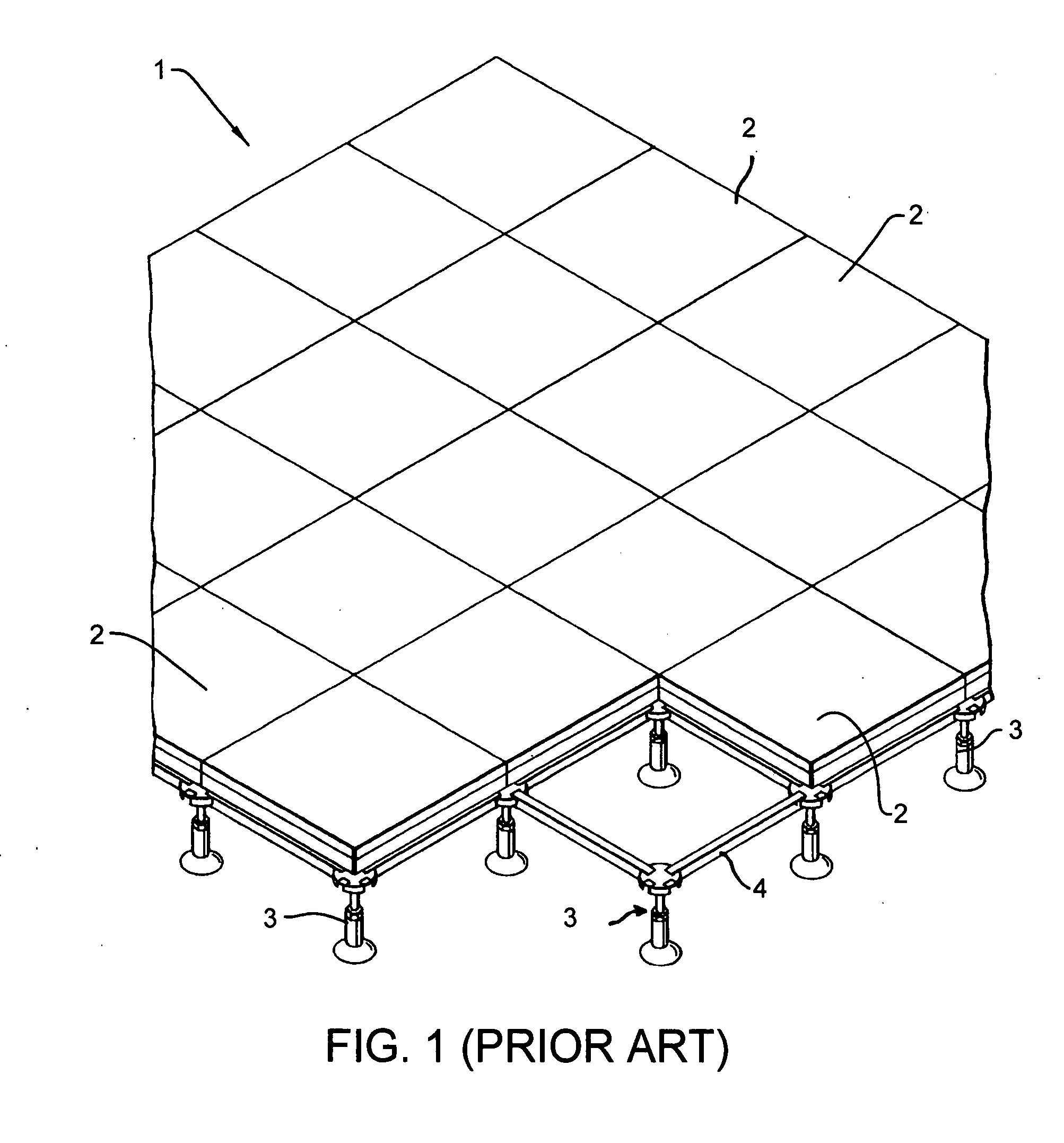
[0056]Referring to FIG. 1, there is illustrated a somewhat conventional raised floor arrangement 1 defined by a plurality of generally square removable floor tiles 2, the latter being supported on a plurality of upright pedestals 3 which are typically arranged in uniformly spaced relationship within rows and columns to define a grid, whereby each pedestal typically cooperates with the corners of up to four floor tiles. The arrangement of FIG. 1 also illustrates horizontally elongate stringers or rails 4 extending between and joined to adjacent pedestals 3, which stringers are frequently utilized to provide supportive engagement for the edge of the floor tiles, although in many systems the stringers are eliminated and the floor tiles are supported entirely by the pedestals. The conventional arrangement of a raised floor as diagrammatically depicted by FIG. 1 is solely for background purposes, and it will be understood that the improved floor system of the present invention as describ...


PUM


Abstract

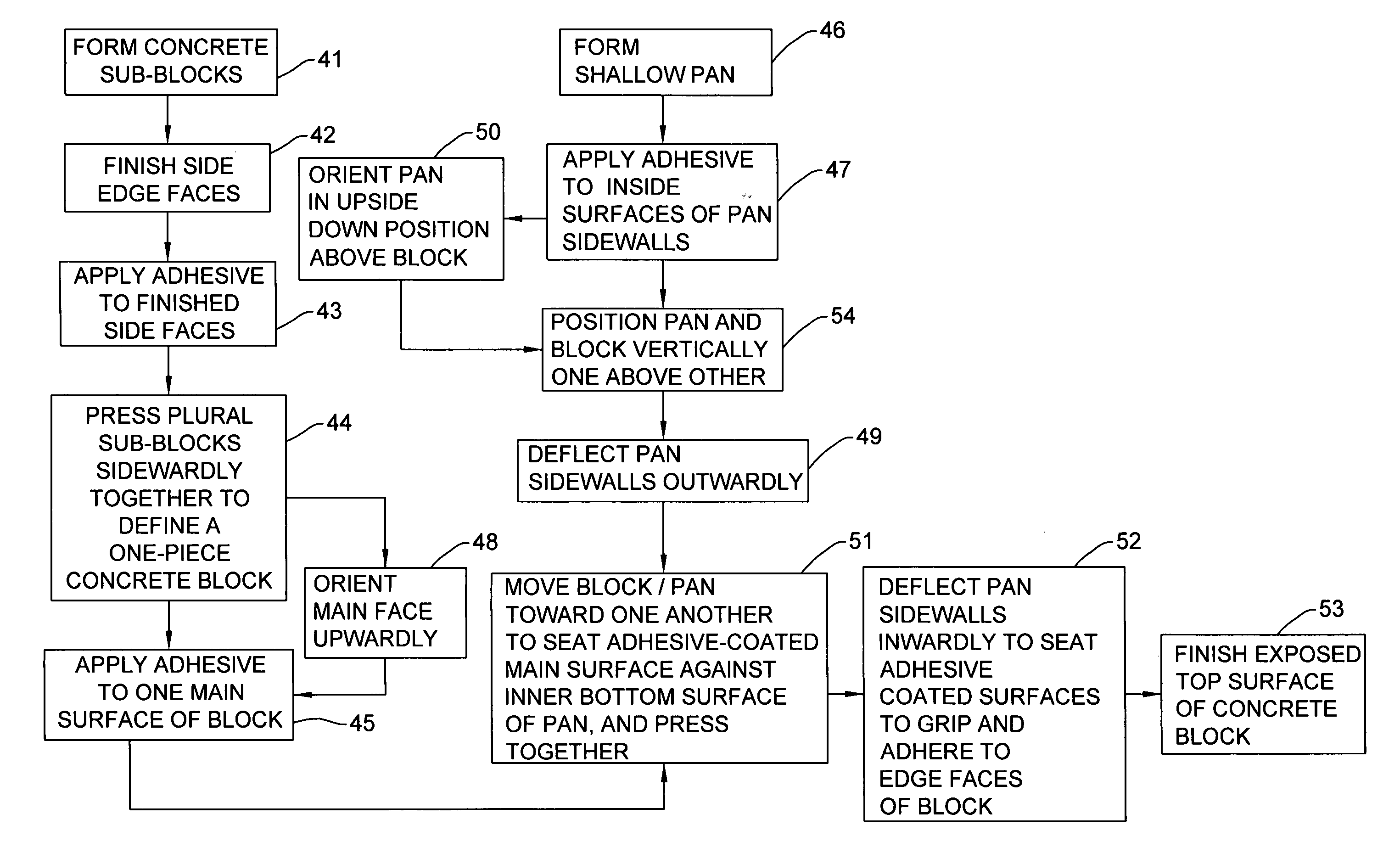
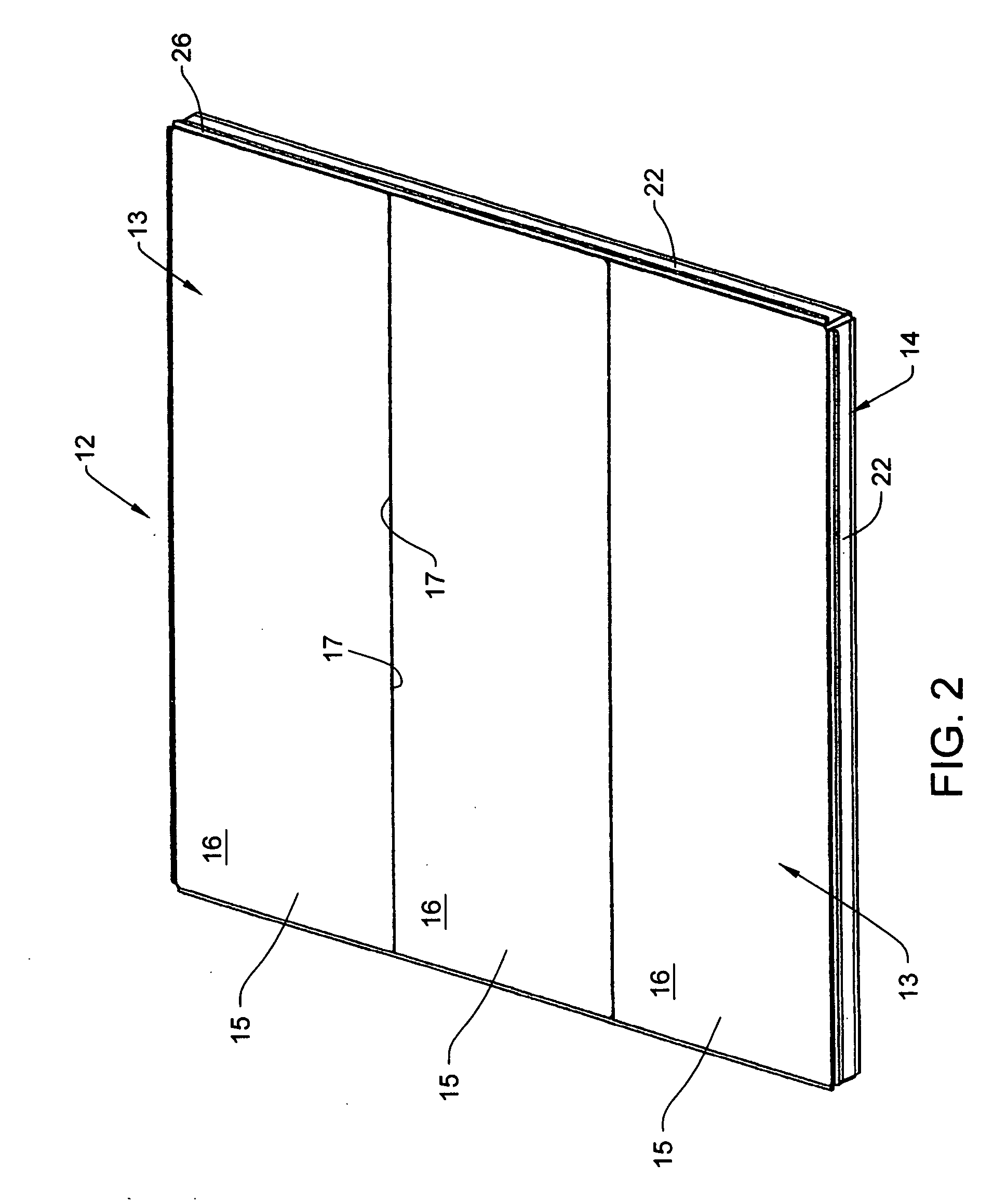
A floor tile for a raised floor. The floor tile is defined by a shallow upwardly-opening metal pan defining a shallow compartment in which a main preformed one-piece concrete block is secured. The main concrete block is preferably formed from a plurality of one-piece preformed concrete sub-blocks which are adhesively adhered in sideward abutting relationship to define a plan profile corresponding to the main concrete block. The main concrete block is then adhesively secured within the compartment of the metal pan.

Description

CROSS REFERENCE TO RELATED APPLICATION[0001]This application claims the benefit of U.S. Provisional Application No. 60 / 997 023, filed Sep. 28, 2007, the disclosure of which is incorporated herein by reference in its entirety.FIELD OF THE INVENTION[0002]This invention relates to improvements with respect to a raised floor system, including improvements relative to floor tiles and the supports therefor, and improvements relative to the manufacturing process for the floor tiles.BACKGROUND OF THE INVENTION[0003]A significant variety of raised floor systems have been developed for use in commercial buildings. Such systems typically employ a plurality of height-adjustable pedestals supported on a main floor in a grid-like arrangement, and a plurality of removable floor tiles supported on the upper ends of the pedestals. The floor tiles are formed using numerous construction techniques, with one common technique employing a formed sheet metal pan defining an upwardly opening compartment wh...

Claims


Application Information

Patent Timeline
IPC IPC(8): E04F15/00E04F15/02E04F15/08E04G11/36
CPCE04F15/02429E04F15/02405
Inventor MCCONNELL, ANTHONYBROWN, RONALD H.GINGRICH, BRYAN R.TUTTLE, ROBERT L.WOELLPER, RANDOLPHYU, X. SHAWN
Owner GLOBAL INTEGRATED FLOORING SOLUTIONS INC
Learn More