
System and method for creating high gloss plastic items via the use of styrenic copolymers as a coextruded layer

a technology of styrenic copolymer and coextrusion layer, which is applied in the field of plastic bottle and other plastic articles formation, can solve the problems of hdpe typical, cracking of polymer, and release of contents

Active Publication Date: 2009-03-26
CHEVRON PHILLIPS CHEMICAL CO LP +1
View PDF13 Cites 5 Cited by
  • Summary
  • Abstract
  • Description
  • Claims
  • Application Information

AI Technical Summary

Problems solved by technology

When the product in contact with the problem material is placed under stress, it may result in cracking of the polymer leading to failure.
This failure may result in the release of the contents.
However, HDPE typically has the disadvantage that formed products have a low surface gloss.
For many applications, the low surface gloss decreases the brilliance and attractiveness of the marketing materials on the exterior of the HDPE bottle.
Unfortunately, however, styrenic copolymers may have significant disadvantages when used as containers for particular materials.
For example, many styrenic copolymers are sensitive to environmental stress cracking and cannot be used for such applications as soap, which may cause the container to fail.
Further, such copolymers may not have the moisture barrier properties to protect some materials from evaporative losses over time.
For example, high water content materials, such as aqueous solutions, may experience noticeable product loss over a shorter period of time when kept in a bottle made from a styrenic copolymer versus a bottle made from HDPE.
However, in addition to having a lower gloss than a polymer made with a large amount of styrene, products made having an outer surface of MDPE may have a waxy surface and problems with label adhesion, for example.
However, these polymers have increased the surface friction of the products, leading to problems with the products feeding through the machinery and equipment required for filling, labeling, or other processing operations.
Further, in many cases, these polymers may be sensitive to scratching, leading to poor surface appearance when the blow molded article reaches the marketing outlet for sale to the end consumer.

Method used


Image

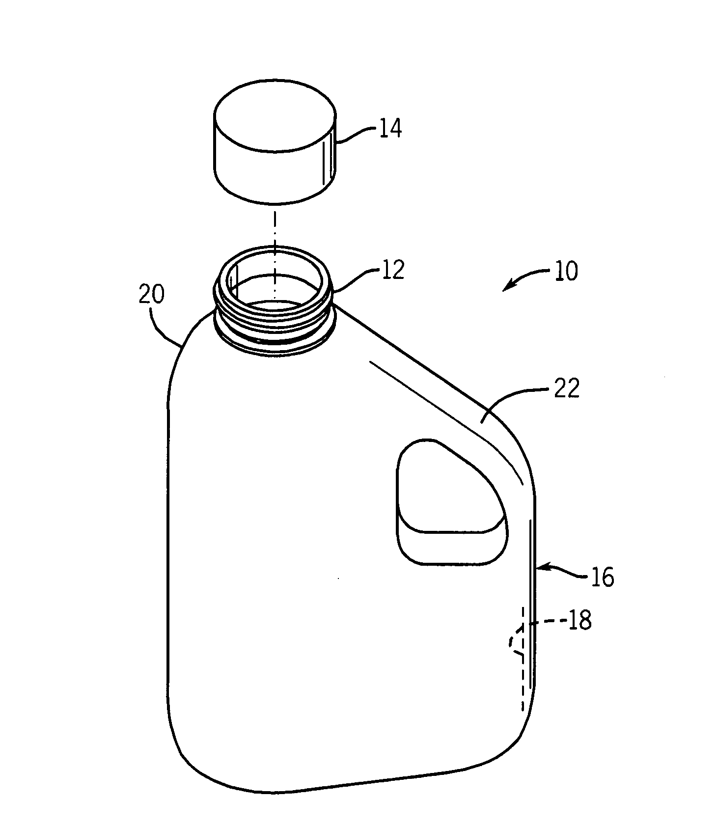
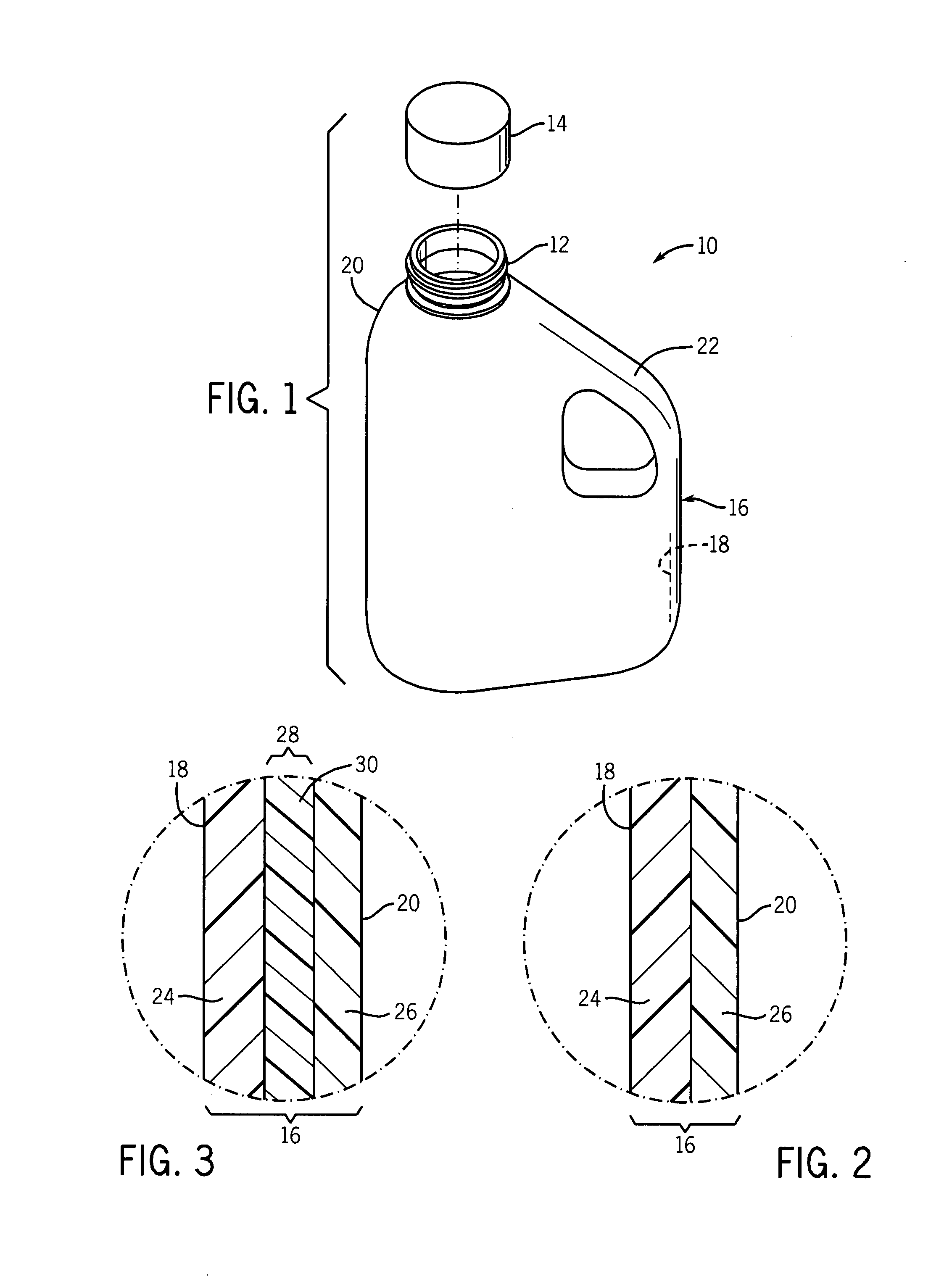
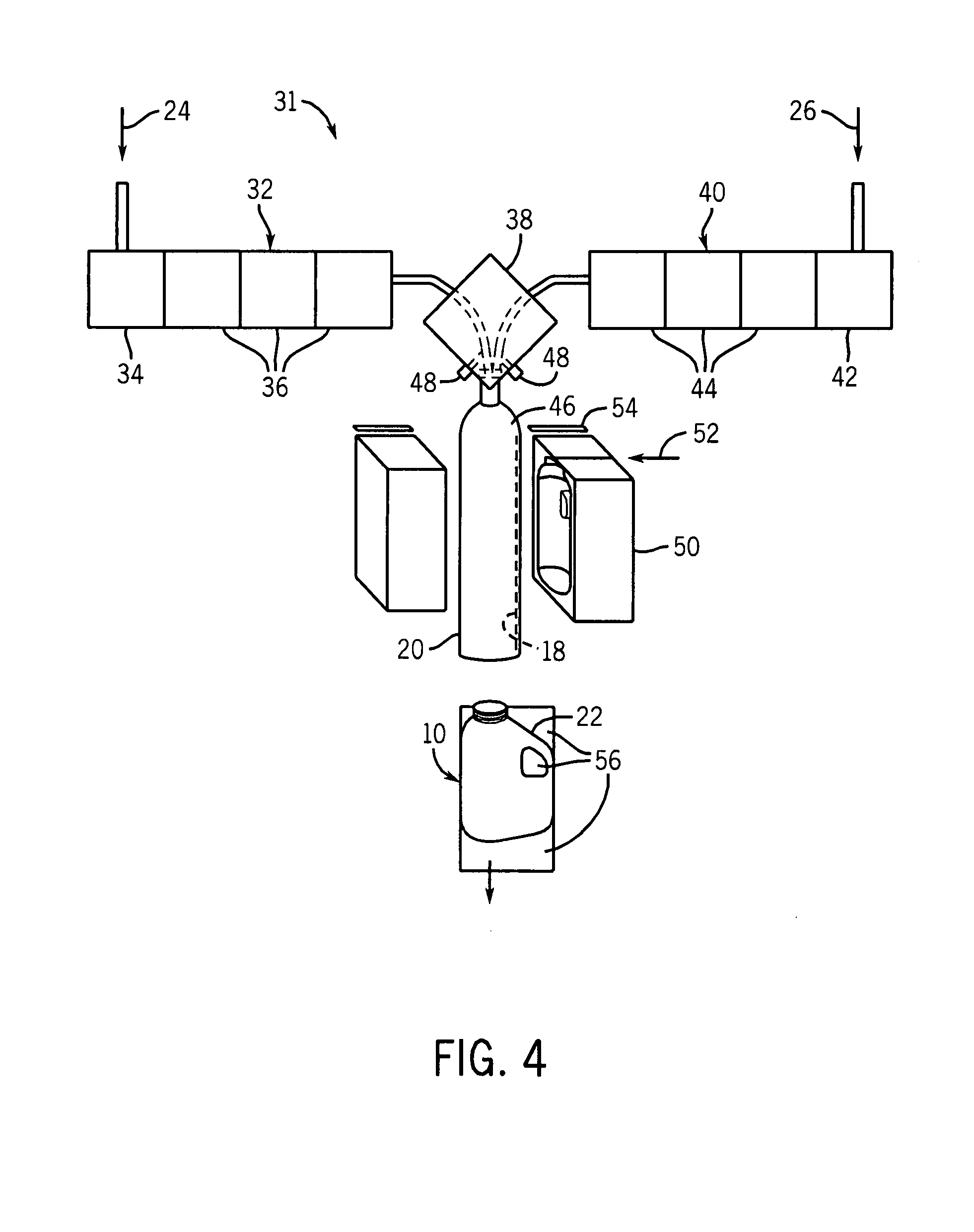
  • System and method for creating high gloss plastic items via the use of styrenic copolymers as a coextruded layer
  • System and method for creating high gloss plastic items via the use of styrenic copolymers as a coextruded layer
  • System and method for creating high gloss plastic items via the use of styrenic copolymers as a coextruded layer

Examples


Embodiment Construction

[0020]One or more specific embodiments of the present invention will be described below. In an effort to provide a concise description of these embodiments, not all features of an actual implementation are described in the specification. It should be appreciated that in the development of any such actual implementation, as in any engineering or design project, numerous implementation-specific decisions must be made to achieve the developers' specific goals, such as compliance with system-related and business-related constraints, which may vary from one implementation to another. Moreover, it should be appreciated that such a development effort might be complex and time consuming, but would nevertheless be a routine undertaking of design, fabrication, and manufacture for those of ordinary skill having the benefit of this disclosure.

[0021]The present techniques include multi-layer plastic structures having a first surface layer (e.g., an internal layer) that includes a high-density ty...


PUM

PropertyMeasurementUnit
densityaaaaaaaaaa
densityaaaaaaaaaa
melt indexaaaaaaaaaa

Abstract

The present techniques provide multi-layer plastic structures and methods for making such. The multi-layer plastic structures include an inner surface made from a polyolefin resin, and resistant to environmental stress cracking, and an outer surface that includes a styrenic copolymer. The outer surface has a kinetic coefficient of friction with itself of 0.42 and a static coefficient of friction with itself of 0.44.

Description

BACKGROUND OF THE INVENTION[0001]1. Field of the Invention[0002]The present techniques relate generally to the formation of plastic bottles and other plastic articles. Specifically, the present techniques relate to the production of plastic bottles and articles having good environmental stress crack resistance and a high gloss outer surface.[0003]2. Description of the Related Art[0004]This section is intended to introduce the reader to various aspects of art which may be related to various aspects of the present invention that are described and / or claimed below. This discussion is believed to be helpful in providing the reader with background information to facilitate a better understanding of the various aspects of the present invention. Accordingly, it should be understood that these statements are to be read in this light, and not as admissions of prior art.[0005]As chemical and petrochemical technologies have advanced, the products of these technologies have become increasing pr...

Claims


Application Information

Patent Timeline
Patent Type & Authority Applications(United States)
IPC IPC(8): B29D22/00B29C48/09B29C48/21B29C48/305B29C48/49B29C48/90
CPCB29C47/0019Y10T428/24942B29C47/065B29C47/145B29C47/56B29C49/0005B29C49/04B29C49/22B29C51/002B29C51/14B29D22/003B29L2031/463B29C47/0816B29C47/906B29C49/50B29C51/02B29C51/082B29C51/421B29C2049/4805Y10T428/1359Y10T428/24992Y10T428/1352Y10T428/24967B29C47/0021B29C48/9135B29C48/914Y10T428/31931B29C48/07B29C48/21B29C48/307B29C48/08B29C48/49B29C48/906B29C48/2556B29C48/09
Inventor CARVELL, LEE A.WANDERLICH, MARKBANOVIC, SUSAN L.JALUTKEWICZ, JAMESREES, CHARLES E.SMITH, MICHAEL A.
Owner CHEVRON PHILLIPS CHEMICAL CO LP
Learn More